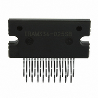
IRAM336-025SB International Rectifier, IRAM336-025SB Datasheet

IRAM336-025SB
Specifications of IRAM336-025SB
Available stocks
Related parts for IRAM336-025SB
IRAM336-025SB Summary of contents
Page 1
... Integrated Power Hybrid IC for Appliance Motor Drive Applications Description International Rectifier’s IRAM336-025SB is a multi-chip Hybrid IC developed for low power appliance motor control applications such as Fans, Pumps, and refrigerator compressors. The compact Single in line (SIP-S) package minimizes PCB space. Several built-in protection features such as temperature feedback, shoot through prevention, under voltage lockout, and shutdown input makes this a very robust solution ...
Page 2
... IRAM336-025SB Internal Electrical Schematic – IRAM336-025SB + Vbus (3) (2) GND VB1 (9) U, VS1 (8) (7) VB2 V, VS2 (6) VB3 (5) W, VS3 (4) Internal to Driver HIN1 (11) HIN2 (12) HIN3 (13) LIN1 (14) LIN2 (15) LIN3 (16) I (10) TRIP Fault/En (17 VDD (18) (19) VSS VS1 VB2 HO2 VS2 VB3 24 HO1 25 VB1 1 VCC ...
Page 3
... V I input voltage ITRIP TRIP Logic input voltage LIN, HIN, Fault/EN F/EN ITRIP F Maximum PWM Carrier Frequency p Note 2: Logic operational for V from COM- (please refer to DT97-3 for more details). www.irf.com IRAM336-025SB . +0.3 V B1,2,3 B1,2,3 -0.3 500 V -0 Lower of (V +15V) or -0.3 ...
Page 4
... IRAM336-025SB Static Electrical Characteristics )=15V, unless otherwise specified. The V BIAS DD BS1,2,3 to all six channels (Static Electrical Characteristics are Based on Driver IC Data Sheet). Symbol Definition V Enable Positive going threshold EN,th+ V Enable Negative going threshold EN,th and V supply undervoltage, Positive going threshold DDUV+, ...
Page 5
... The shaded area indicates that both high-side and low-side switches are off and therefore the half- Note 3: bridge output voltage would be determined by the direction of current flow in the load. www.irf.com Figure 1. Input/Output Timing Diagram IRAM336-025SB 5 ...
Page 6
... IRAM336-025SB HIN1,2,3 LIN1,2,3 I TRIP U,V,W The shaded area indicates that both high-side and low-side switches are off and therefore the half- Note 4: bridge output voltage would be determined by the direction of current flow in the load. Input-Output Logic Level Table I FLT- EN HIN1,2,3 LIN1,2,3 TRIP ...
Page 7
... Typical Application Circuit – IRAM336-025SB Application Circuit Recommendation 1. Electrolytic bus capacitors should be mounted as close to the module bus terminals as possible to reduce ringing and EMI problems. Additional high frequency ceramic capacitor mounted close to the module pins will further improve performance order to provide good decoupling between VCC-VSS and Vb-Vs terminals, the capacitors shown connected between these terminals should be located very close to the module pins. frequency capacitors, typically 0.1µ ...
Page 8
... IRAM336-025SB Module Pin-Out Description Pin Name TRIP H 11 IN1 H 12 IN2 H 13 IN3 L 14 IN1 15 L IN2 L 16 IN3 17 FAULT/ Description Temperature Feedback Negative Bus Input Voltage Positive Bus Input Voltage Output 3 - High Side Floating Supply Offset Voltage High Side Floating Supply Voltage 3 ...
Page 9
... Integrated Bootstrap Functionality The internal Driver IC in the IRAM336-025SB embeds an integrated bootstrap FET that allows an alternative drive of the bootstrap supply for a wide range of applications. There is one bootstrap FET for each channel and it is connected between each of the floating supply (VB1, VB2, VB3) and Vcc as shown in Figure 3. ...
Page 10
... IRAM336-025SB 1.6 1.4 1.2 1 0.8 0.6 0.4 0 Figure 5. Maximum Sinusoidal Phase Current vs. PWM Switching Frequency Sinusoidal Modulation 150ºC J 1.2 Sinusoidal Modulation 1 0.8 0.6 0.4 0 Figure 6. Maximum Sinusoidal Phase Current vs. Modulation Frequency Sinusoidal Modulation 80º 90º 100º PWM Sw itching Frequency - kHz ...
Page 11
... Figure 8. Total Power Losses vs. Output Phase Current Sinusoidal Modulation, V www.irf.com PWM Sw itching Frequency - kHz + =360V, T =150°C, MI=0.8, PF=0.6 J 0.4 0.6 0.8 1 Output Phase Current - A RMS + =360V, T =150°C, MI=0.8, PF=0.6 J IRAM336-025SB I = 1.2A OUT I = 1.0A OUT I = 0.8A OUT 20kHz PWM F = 16kHz PWM F = 12kHz PWM 1 ...
Page 12
... IRAM336-025SB 150 125 T is limited to 100ºC C 100 0.2 Figure 9. Maximum Allowable Case Temperature vs. Output RMS Current per Phase Sinusoidal Modulation, V 160 T = 1.181 avg 150 140 130 120 110 100 Internal Therm istor Tem perature Equivalent Read Out - °C Figure 10. Estimated Maximum MOSFET Junction Temperature vs. Thermistor Temperature ...
Page 13
... Therm istor Tem perature - °C 1.5µ PWM Frequency - kHz IRAM336-025SB 90 100 110 120 130 140 150 1µ ...
Page 14
... IRAM336-025SB Figure 13. Switching Parameter Definitions V DS 50 Figure 13a. Input to Output propagation turn-on delay time. Figure 13c. Diode Reverse Recovery 50 OFF Figure 13b. Input to Output propagation turn-off delay time. www.irf.com ...
Page 15
... Figure CT1. Switching Loss Circuit www.irf.com IRAM336-025SB 15 ...
Page 16
... IRAM336-025SB Package Outline IRAM336-025SB note3 IRAM136-025SB note2 Data and Specifications are subject to change without notice. For mounting instruction see AN-1049. IR WORLD HEADQUARTERS: 233 Kansas St., El Segundo, California 90245, USA Tel: (310) 252-7105 16 note4 note1: Unit Tolerance is +0.4mm, Unless Otherwise Specified. note2: Mirror Surface Mark indicates Pin1 Identification. ...


