VSKT500-12 Vishay, VSKT500-12 Datasheet
VSKT500-12
Specifications of VSKT500-12
IRKT500-12
IRKT500-12


Related parts for VSKT500-12


VSKT500-12 Summary of contents
Page 1
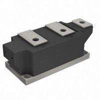
... VSKT500-..PbF, VSKH500-..PbF, VSKL500-..PbF Thyristor/Diode and Thyristor/Thyristor (SUPER MAGN-A-PAK Power Modules), 500 A SUPER MAGN-A-PAK PRODUCT SUMMARY T(AV) F(AV) MAJOR RATINGS AND CHARACTERISTICS SYMBOL °C T(AV) F(AV) I T(RMS TSM Range RRM T Range Stg T Range J ELECTRICAL SPECIFICATIONS VOLTAGE RATINGS V /V RRM ...
Page 2
... VSKT500-..PbF, VSKH500-..PbF, VSKL500-..PbF Vishay Semiconductors ON-STATE CONDUCTION PARAMETER Maximum average on-state current at case temperature Maximum RMS on-state current Maximum peak, one-cycle, non-repetitive on-state surge current 2 Maximum I t for fusing t for fusing 2 Maximum I Low level value or threshold voltage ...
Page 3
... VSKT500-..PbF, VSKH500-..PbF, VSKL500-..PbF Thyristor/Diode and Thyristor/Thyristor (SUPER MAGN-A-PAK Power Modules), 500 A TRIGGERING PARAMETER Maximum peak gate power Maximum peak average gate power Maximum peak positive gate current Maximum peak positive gate voltage Maximum peak negative gate voltage Maximum DC gate current required to trigger ...
Page 4
... VSKT500-..PbF, VSKH500-..PbF, VSKL500-..PbF Vishay Semiconductors 130 VSK.500.. S eries R (DC) = 0.065 K/ W thJC 120 110 Conduc tion Angle 100 90 30° 80 60° 90° 120° 100 200 300 400 Average On-state Current (A) Fig Current Ratings Characteristics 130 VSK.500.. S eries R (DC ...
Page 5
... VSKT500-..PbF, VSKH500-..PbF, VSKL500-..PbF Thyristor/Diode and Thyristor/Thyristor (SUPER MAGN-A-PAK Power Modules), 500 A 750 700 650 600 550 500 Conduction Angle 450 400 350 300 250 200 150 100 100 200 300 400 500 600 700 800 T otal R MS Output Current (A) ...
Page 6
... VSKT500-..PbF, VSKH500-..PbF, VSKL500-..PbF Vishay Semiconductors 10000 T = 25°C 1000 130°C J VSK.500.. S eries Per Junction 100 0.5 1 1.5 2 2.5 3 Instantaneous On-s tate Voltage (V) Fig On-State Voltage Drop Characteristics 100 R ectangular gate pulse a) R ecommended load line for rated di 20V, 10ohms; tr<=1 µs b) Recommended load line for < ...
Page 7
... VSKT500-..PbF, VSKH500-..PbF, VSKL500-..PbF Thyristor/Diode and Thyristor/Thyristor (SUPER MAGN-A-PAK Power Modules), 500 A CIRCUIT CONFIGURATION VSKT (K1) 7 (K2) 5 (G1) 6 (G2) Dimensions Document Number: 94420 For technical questions within your region, please contact one of the following: Revision: 02-Jul-10 DiodesAmericas@vishay.com, DiodesAsia@vishay.com, VSKH (K1) ...
Page 8
... Vishay product could result in personal injury or death. Customers using or selling Vishay products not expressly indicated for use in such applications their own risk and agree to fully indemnify and hold Vishay and its distributors harmless from and against any and all claims, liabilities, expenses and damages arising or resulting in connection with such use or sale, including attorneys fees, even if such claim alleges that Vishay or its distributor was negligent regarding the design or manufacture of the part ...