GP1A50HR Sharp Microelectronics, GP1A50HR Datasheet

PHOTOINTER OPIC SLOT 3.0MM PCB

GP1A50HR

Manufacturer Part Number
GP1A50HR
Description
PHOTOINTER OPIC SLOT 3.0MM PCB
Manufacturer
Sharp Microelectronics
Series
OPIC™r
Datasheet

Specifications of GP1A50HR

Sensing Distance
0.118" (3mm)
Sensing Method
Transmissive
Output Configuration
Pull-Up Resistor, Buffer
Mounting Type
Through Hole
Current - Supply
1.7mA
Voltage - Supply
4.5 V ~ 17 V
Response Time
1µs, 0.05µs
Package / Case
PCB Mount
Lead Free Status / RoHS Status
Contains lead / RoHS non-compliant
Other names
425-1073-5

Available stocks

Company
Part Number
Manufacturer
Quantity
Price
Part Number:
GP1A50HR
Manufacturer:
KODENSHI
Quantity:
100 000
Part Number:
GP1A50HRJ00F
Manufacturer:
Sharp Microelectronics
Quantity:
1 000
Part Number:
GP1A50HRJ00F
Manufacturer:
VISHAY
Quantity:
14 000
GP1A50HR/GP1A51HR
GP1A52HR/GP1A53HR
1. High sensing accuracy ( Slit width : 0.5mm )
2. LSTTL and TTL compatible output
3.
“ In the absence of confirmation by device specification sheets, SHARP takes no responsibility for any defects that occur in equipment using any of SHARP's devices, shown in catalogs,
data books, etc. Contact SHARP in order to obtain the latest version of the device specification sheets before using any SHARP's device.”
GP1A50HR
GP1A52HR
Marking :
Features
Outline Dimensions
Both-sides mounting type : GP1A50HR ( Gap: 3mm )
Either-side mounting type : GP1A51HR ( Gap: 3mm )
PWB mounting type : GP1A52HR ( Gap: 3mm )
5 - 0.4
5 - 0.4
1A50HR
( 1.5 )
4
+ 0.3
- 0.1
+ 0.3
- 0.1
2 -
19.0
2
1
A52
12.2
5
3
3.0
12.2
25.0
3.0
( 1.5 )
( 9.2 )
( 9.2 )
+ 0.2
- 0.1
3.2
4 5
± 0.2
+ 0.2
± 0.3
- 0.1
± 0.3
± 0.3
3
S
± 0.2
1
2
GP1A53HR ( Gap: 5mm )
* ( ) : Reference dimensions
2 - C2.0
*Unspecified tolerances shall be as
* ( ) : Reference dimensions
*Unspecified tolerances shall be as
Dimensions ( d ) Tolerance
18.0< d<=25.0 ± 0.025
Dimensions ( d ) Tolerance
6.0< d<=18.0
6.0< d<=18.0
( Both sides
and detector )
of emitter
Slit width
( 1.27 )
d<=6.0
d<=6.0
( 1.27 )
0.5
0.5
5 - 0.45
Slit width
( Both sides of
( 1.27 )
emitter and
detector )
5.0
± 0.1
± 0.2
± 0.1
± 0.2
( 1.27 )
5 - 0.45
C1.0
+ 0.3
- 0.1
follows:
follows:
+ 0.3
- 0.1
GP1A51HR
GP1A53HR
GP1A50HR/GP1A51HR/GP1A52HR/GP1A53HR
5 - 0.4
5 - 0.4
1. OA equipment, such as printers, facsimiles,
2. VCRs
*“ OPIC” ( Optical IC ) is a trademark of the SHARP Corporation.
( 1.5 )
etc.
+ 0.3
- 0.1
5
4
3
Applications
An OPIC consists of a light-detecting element and signal-
processing circuit integrated onto a single chip.
+ 0.3
- 0.1
( 1.5 )
4
2.0
12.2
3.0
( 9.2 )
A53
5
3
13.7
+ 0.2
- 0.1
5.0
± 0.3
( 10.3 )
+ 0.2
- 0.1
± 0.3
S
1
2
1
2
* ( ) : Reference dimensions
*Unspecified tolerances shall be as
( Both sides
Dimensions ( d ) Tolerance
18.0< d<=25.0
6.0 < d<=18.0
of emitter
and detector )
*Unspecified tolerances shall be as follows :
Slit width
6.0< d<=18.0
2 - ( 1.27 )
OPIC
Photointerrupter
12.0
18.0
5.0
d<=6.0
( 1.27 )
d<=6.0
( Both sides of
0.5
Slit width
emitter and
detector )
0.5
5.2
5 - 0.45
( 1.27 )
± 0.25
± 0.1
± 0.2
± 0.1
± 0.2
5 - 0.45
C1.0
2-
( Unit : mm )
+ 0.3
- 0.1
3.2
+ 0.3
- 0.1
± 0.2
follows:

Related parts for GP1A50HR

GP1A50HR Summary of contents

Page 1

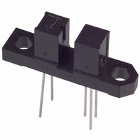
... GP1A50HR/GP1A51HR GP1A52HR/GP1A53HR Features 1. High sensing accuracy ( Slit width : 0.5mm ) 2. LSTTL and TTL compatible output Both-sides mounting type : GP1A50HR ( Gap: 3mm ) 3. Either-side mounting type : GP1A51HR ( Gap: 3mm ) PWB mounting type : GP1A52HR ( Gap: 3mm ) GP1A53HR ( Gap: 5mm ) Outline Dimensions GP1A50HR ± 0.2 19.0 ± ...

Page 2

... High Low” propagation delay time Rise time Fall time *3 I represents forward current when output changes from low to high. FLH *4 I represents forward current when output changes from high to low. Hysteresis stands for I FHL *5 GP1A53HR Condition Response time CCH GP1A50HR/GP1A51HR/GP1A52HR/GP1A53HR GND Symbol ...

Page 3

... Ambient temperature T a Fig. 3 Low Level Output Current vs. Ambient Temperature Ambient temperature T a GP1A50HR/GP1A51HR/GP1A52HR/GP1A53HR Symbol Operating temp 70˚ Fig. 2 Output Power Dissipation vs 100 ( ˚C ) Fig. 4 Forward Current vs. Forward Voltage 75 85 100 ( ˚C ) MIN. MAX. - 16.0 10.0 20.0 Ambient Temperature 300 250 ...

Page 4

... Ambient Temperature 1.6 1.4 I FLH 1.2 1.0 I FHL 0.8 0 25˚C FLH a 0 ˚C ) Ambient temperature T a Ambient Temperature 0.6 V 0.5 0.4 0 30mA OL 0.2 0 ˚C ) Ambient temperature GP1A50HR/GP1A51HR/GP1A52HR ) 280 25˚C PHL PLH Forward current I F 100 = 5V CC 16mA 5mA 100 60 ...

Page 5

... Vcc and GND near the device case of cleaning, use only the following type of cleaning solvent. Ethyl alcohol, Methyl alcohol, Isopropyl alcohol ( for other general cautions refer to the chapter “ Precautions for Use ” . GP1A50HR/GP1A51HR/GP1A52HR/GP1A53HR Fig.12 Rise Time, Fall Time vs. t PHL ...

Page 6

Application Circuits NOTICE The circuit application examples in this publication are provided to explain representative applications of SHARP devices and are not intended to guarantee any circuit design or license any intellectual property rights. SHARP takes no responsibility for any ...

Related keywords