GP1S562 Sharp Microelectronics, GP1S562 Datasheet

PHOTOINTERRUPTER SLOT 3.0MM PCB

GP1S562

Manufacturer Part Number
GP1S562
Description
PHOTOINTERRUPTER SLOT 3.0MM PCB
Manufacturer
Sharp Microelectronics
Type
Unamplifiedr
Datasheet

Specifications of GP1S562

Rohs Status
RoHS non-compliant
Sensing Distance
0.118" (3mm)
Sensing Method
Transmissive
Output Configuration
Phototransistor
Current - Dc Forward (if)
50mA
Current - Collector (ic) (max)
20mA
Voltage - Collector Emitter Breakdown (max)
35V
Response Time
3µs, 4µs
Mounting Type
Snap-In
Package / Case
PCB Mount
Operating Temperature
-25°C ~ 85°C
Other names
425-1054-5

Available stocks

Company
Part Number
Manufacturer
Quantity
Price
Part Number:
GP1S562
Manufacturer:
SHARP
Quantity:
1
GP1S562
1. Compact package
2. With a spacer
3. With a hook for temporary
1. Floppy disk drivers
2. VCRs
*1 Pulse width<=100 s, Duty ratio : 0.01
*2 For 5 seconds
“ In the absence of confirmation by device specification sheets, SHARP takes no responsibility for any defects that occur in equipment using any of SHARP's devices, shown in catalogs,
data books, etc. Contact SHARP in order to obtain the latest version of the device specification sheets before using any SHARP's device.”
Input
Output
Features
installation to PWB
Applications
Absolute Maximum Ratings
*1
*2
Forward current
Reverse voltage
Power dissipation
Collecotr-emitter voltage
Emitter-collector voltage
Collector current
Collector power dissipation
Operating temperature
Peak forward current
Storage temperature
Soldering temperature
Parameter
Symbol
V
V
T
T
T
I
V
P
I
I
CEO
ECO
P
FM
opr
stg
sol
F
C
R
C
Compact Photointerrupter with
Holders
- 40 to + 100
Outline Dimentions
- 25 to + 85
6.2
1
Rating
( 2.54 )
4 - 0.45
260
50
75
35
20
75
1
6
6
+ 0.3
- 0.2
2 - 0.8
( Ta = 25˚C )
2 - 1
0.5
2
1
0.3
( Top of Hook )
Unit
mW
mW
mA
mA
˚C
˚C
˚C
A
V
V
V
1
8.4
7 ± 0.3
1
( 4.75 )
12
10
12
+ 0.1
- 0.2
3
+ 0.3
- 0.4
4 - 0.25
3
4
0.6
* Unspecified tolerance :± 0.2mm
* ( ) : Reference dimensions
* Please be careful not to receive
external disturbing light because
the top and back face of emitter
and detector elements are not
covered by case.
+ 0.3
- 0.2
1 Anode
2 Cathode
Internal connection diagram
1
2
( Slit width )
2 - 0.8
( Unit : mm )
GP1S562
± 0.1
4 Collector
3 Emitter
0.1
4.2
4
3

Related parts for GP1S562

GP1S562 Summary of contents

Page 1

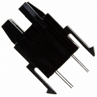
... ECO ˚C opr 100 ˚C stg T 260 ˚C sol GP1S562 ( Unit : mm ) Internal connection diagram Anode 4 Collector 2 Cathode 3 Emitter 4.2 ± 0.1 0 0.8 ( Slit width ) 0 0.25 - 0.2 * Unspecified tolerance :± 0.2mm * ( ) : Reference dimensions 3 * Please be careful not to receive external disturbing light because ...

Page 2

... MIN. TYP 20mA 1 1.4mA - - C = 2mA - Ambient Temperature 120 100 ˚C ) Ambient temperature T a 500 T = 75˚C a 200 25˚C 50˚C 0˚C 100 - 20˚ 0.5 1.0 1.5 2.0 2 Forward voltage V F GP1S562 ( Ta = 25˚C ) MAX. Unit 1 100 nA 8 100 3.0 3.5 ...

Page 3

... Load resistance R L Fig. 6 Collector Current vs. Collector-emitter 25˚ Fig. 8 Collector-emitter Saturation Voltage vs. = ˚C ) Test Circuit for Response Time Input Voltage 50mA F 40mA 8 30mA 6 20mA 4 10mA Collector-emitter voltage V CE Ambient Temperature 0.2 0.15 0 ˚C ) Ambient temperature T a Input Output Output GP1S562 = 25˚ 10% 90 ...

Page 4

... Fig.10 Frequency Response 10k - Frequency Please refer to the chapter “Precautions for Use ”. Fig.11 Collector Dark Current vs 10mA 25˚ 100 Ambient Temperature - 10V - ˚C ) Ambient temperature T a GP1S562 100 ...

Page 5

Application Circuits NOTICE The circuit application examples in this publication are provided to explain representative applications of SHARP devices and are not intended to guarantee any circuit design or license any intellectual property rights. SHARP takes no responsibility for any ...

Related keywords