A22K-K Omron, A22K-K Datasheet - Page 161
A22K-K
Manufacturer Part Number
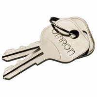
A22K-K
Description
REPLACEMENT KEY A22 SERIES 2 PCS
Manufacturer
Omron
Type
Pushbutton Switchr
Specifications of A22K-K
Accessory Type
Replacement Key
Termination Style
Crimp
For Use With/related Products
A22K Series
For Use With
A22K-3MC-20 - SWITCH KEYLOCK 3POS ALT DPST-NOA22K-3MC-10 - SWITCH KEYLOCK 3POS ALT SPST-NOA22K-3MC-02 - SWITCH KEYLOCK 3POS ALT DPST-NCA22K-3MC-01 - SWITCH KEYLOCK 3POS ALT SPST-NCA22K-3AC-20 - SWITCH KEYLOCK 3POS MOM DPST-NOA22K-3AC-10 - SWITCH KEYLOCK 3POS MOM SPST-NOA22K-3AC-02 - SWITCH KEYLOCK 3POS MOM DPST-NCA22K-2ML-20 - SWITCH KEYLOCK 2POS ALT DPST-NOA22K-2ML-11 - SWITCH KEYLOC 2POS ALT DPST-NO/CA22K-2ML-02 - SWITCH KEYLOCK 2POS ALT DPST-NCA22K-2ML-01 - SWITCH KEYLOCK 2POS ALT SPST-NCA22K-2M-20 - SWITCH KEYLOCK 2POS ALT DPST-NOA22K-2M-11 - SWITCH KEYLOC 2POS ALT SPST-NO/CA22K-2M-02 - SWITCH KEYLOCK 2POS ALT DPST-NCA22K-2M-01 - SWITCH KEYLOCK 2POS ALT SPST-NCA22K-2AL-20 - SWITCH KEYLOCK 2POS MOM DPST-NOA22K-2AL-11 - SWITCH KEYLOC 2POS MOM SPST-NO/CA22K-2AL-02 - SWITCH KEYLOCK 2POS MOM DPST-NCA22K-2AL-01 - SWITCH KEYLOCK 2POS MOM SPST-NCA22K-3ML - SWITCH UNIT KEYLOCK ALT 3POS BLKA22K-3MC - SWITCH UNIT KEYLOCK ALT 3POS BLKA22K-3M - SWITCH UNIT KEYLOCK ALT 3POS BLKA22K-3AC - SWITCH UNIT KEYLOCK MOM 3POS BLKA22K-2ML - SWITCH UNIT KEYLOCK ALT 2POS BLKA22K-2M - SWITCH UNIT KEYLOCK ALT 2POS BLKA22K-2AL - SWITCH UNIT KEYLOCK MOM 2POS BLKZ1536 - SWITCH KEY 3-POS SPST-NO/NC BLKZ1535 - SWITCH KEY 3-POS SPST-NO/NC BLKZ1534 - SWITCH KEY 3-POS SPST-NO/NC BLKZ1533 - SWITCH KEY 3-POS SPST-NO/NC BLKZ1532 - SWITCH KEY 2POS SPST-NO BLACKZ1531 - SWITCH KEY 2POS SPST-NO BLACKZ1530 - SWITCH KEY 2POS SPST-NO BLACK
Lead Free Status / RoHS Status
Lead free / RoHS Compliant
Other names
A22K-K
A22KK
Z1669
A22KK
Z1669


Installation
Common to A22, A22S/W, A22K, M22, and A22E
Panel Hole Dimensions
For 25-dia. holes, always use 25-dia. Rings. (Since the cutout dimen-
sions are large, IP65 cannot be guaranteed unless 25-dia. Rings are
used.)
If outer surface treatment such as coating is performed for the panel,
the panel dimensions after outer surface treatment must meet the
specified panel dimensions.
Note: Recommended panel thickness: 1 to 5 mm.
Matrix Installation
1. The following panel hole dimensions apply when Switch Unit and
the Standard-size Legend Plate Frame and Lock Ring are
mounted, and lead wires are connected directly to the Switch
Block.
Mounting to the Panel
22 dia.
A
25 dia.
2. The following panel hole dimensions apply when the Large-size
Pitches A and B between the centers of the mounting holes are as
follows:
For 1. above:
For 2. above:
Note: 1. The above dimensions are the minimum dimensions for
A22-10, A22-10S, A22-01, A22-01S
A22-20, A22-20S, A22-02, A22-02S, A22-11,
A22-11S
Bare crimp termi-
nals
Crimp terminals
with insulating
sheath
Legend Plate Frame is mounted, and when crimp terminals are
connected to the Switch Block terminals.
Type of crimp
terminal
2. With pushbuttons of external dimensions greater than
3. When using a pushbutton with external dimensions exceed-
when the wires described under Applicable Wire Size on
page 165 are used. If a different wires are used, the wiring
dimensions may be different so determine an appropriate
pitch before setup.
30 mm, set the pitch according to the dimensions. (When
using matrix installation for the A22-M@, mount with a pitch
of 40 mm instead of 30 mm in the diagram above.)
ing 30 mm, use a pitch appropriate for the pushbutton.
Switch Blocks
A22-10, A22-10S, A22-01,
A22-01S
A22-20, A22-20S, A22-02,
A22-02S, A22-11, A22-11S
A22-10, A22-10S, A22-01,
A22-01S
A22-20, A22-20S, A22-02,
A22-02S, A22-11, A22-11S
Switch Blocks
B
45 mm min.
55 mm min.
51 mm min.
61 mm min.
60 mm min.
70 mm min.
A
B
159
Related parts for A22K-K
Image
Part Number
Description
Manufacturer
Datasheet
Request
R

Part Number:
Description:
SWITCH KEY 2POS SPST-NO BLACK
Manufacturer:
Omron
Datasheet:

Part Number:
Description:
SWITCH KEYLOCK 2POS MOM SPST-NC
Manufacturer:
Omron
Datasheet:
Part Number:
Description:
SWITCH KEYLOCK 2POS ALT SPST-NC
Manufacturer:
Omron
Datasheet:
Part Number:
Description:
SWITCH KEYLOCK 2POS ALT SPST-NC
Manufacturer:
Omron
Datasheet:

Part Number:
Description:
SWITCH KEY 3-POS SPST-NO/NC BLK
Manufacturer:
Omron
Datasheet:
Part Number:
Description:
SWITCH KEYLOCK 3POS ALT DPST-NO
Manufacturer:
Omron
Datasheet:
Part Number:
Description:
SWITCH KEYLOCK 2POS MOM DPST-NC
Manufacturer:
Omron
Datasheet:

Part Number:
Description:
SWITCH KEYLOC 2POS MOM SPST-NO/C
Manufacturer:
Omron
Datasheet:
Part Number:
Description:
SWITCH KEYLOCK 2POS MOM DPST-NO
Manufacturer:
Omron
Datasheet:
Part Number:
Description:
SWITCH KEYLOCK 2POS ALT DPST-NC
Manufacturer:
Omron
Datasheet:
Part Number:
Description:
SWITCH PB RND MOM SPST-NO/NC RED
Manufacturer:
Omron
Datasheet:

Part Number:
Description:
SWITCH PB ROUND ALT SPST-NO BLUE
Manufacturer:
Omron
Datasheet:

Part Number:
Description:
SWITCH PB ROUND ALT SPST-NO BLK
Manufacturer:
Omron
Datasheet:

Part Number:
Description:
SWITCH PB ROUND ALT SPST-NO GRN
Manufacturer:
Omron
Datasheet:

Part Number:
Description:
SWITCH PB ROUND ALT SPST-NO RED
Manufacturer:
Omron
Datasheet: