A22K-K Omron, A22K-K Datasheet - Page 17
A22K-K
Manufacturer Part Number
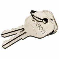
A22K-K
Description
REPLACEMENT KEY A22 SERIES 2 PCS
Manufacturer
Omron
Type
Pushbutton Switchr
Specifications of A22K-K
Accessory Type
Replacement Key
Termination Style
Crimp
For Use With/related Products
A22K Series
For Use With
A22K-3MC-20 - SWITCH KEYLOCK 3POS ALT DPST-NOA22K-3MC-10 - SWITCH KEYLOCK 3POS ALT SPST-NOA22K-3MC-02 - SWITCH KEYLOCK 3POS ALT DPST-NCA22K-3MC-01 - SWITCH KEYLOCK 3POS ALT SPST-NCA22K-3AC-20 - SWITCH KEYLOCK 3POS MOM DPST-NOA22K-3AC-10 - SWITCH KEYLOCK 3POS MOM SPST-NOA22K-3AC-02 - SWITCH KEYLOCK 3POS MOM DPST-NCA22K-2ML-20 - SWITCH KEYLOCK 2POS ALT DPST-NOA22K-2ML-11 - SWITCH KEYLOC 2POS ALT DPST-NO/CA22K-2ML-02 - SWITCH KEYLOCK 2POS ALT DPST-NCA22K-2ML-01 - SWITCH KEYLOCK 2POS ALT SPST-NCA22K-2M-20 - SWITCH KEYLOCK 2POS ALT DPST-NOA22K-2M-11 - SWITCH KEYLOC 2POS ALT SPST-NO/CA22K-2M-02 - SWITCH KEYLOCK 2POS ALT DPST-NCA22K-2M-01 - SWITCH KEYLOCK 2POS ALT SPST-NCA22K-2AL-20 - SWITCH KEYLOCK 2POS MOM DPST-NOA22K-2AL-11 - SWITCH KEYLOC 2POS MOM SPST-NO/CA22K-2AL-02 - SWITCH KEYLOCK 2POS MOM DPST-NCA22K-2AL-01 - SWITCH KEYLOCK 2POS MOM SPST-NCA22K-3ML - SWITCH UNIT KEYLOCK ALT 3POS BLKA22K-3MC - SWITCH UNIT KEYLOCK ALT 3POS BLKA22K-3M - SWITCH UNIT KEYLOCK ALT 3POS BLKA22K-3AC - SWITCH UNIT KEYLOCK MOM 3POS BLKA22K-2ML - SWITCH UNIT KEYLOCK ALT 2POS BLKA22K-2M - SWITCH UNIT KEYLOCK ALT 2POS BLKA22K-2AL - SWITCH UNIT KEYLOCK MOM 2POS BLKZ1536 - SWITCH KEY 3-POS SPST-NO/NC BLKZ1535 - SWITCH KEY 3-POS SPST-NO/NC BLKZ1534 - SWITCH KEY 3-POS SPST-NO/NC BLKZ1533 - SWITCH KEY 3-POS SPST-NO/NC BLKZ1532 - SWITCH KEY 2POS SPST-NO BLACKZ1531 - SWITCH KEY 2POS SPST-NO BLACKZ1530 - SWITCH KEY 2POS SPST-NO BLACK
Lead Free Status / RoHS Status
Lead free / RoHS Compliant
Other names
A22K-K
A22KK
Z1669
A22KK
Z1669


Technical Information
Connection of Different Power Supplies
The DC and AC power may be mixed for the circuit shown below.
Contact Protective Circuit
Apply a contact protective circuit to extend the contact life, prevent noise, and suppress the generation of carbide or nitric acid. Be sure to apply
the contact protective circuit correctly, otherwise an adverse effect may occur.
The following provides typical examples of contact protective circuits. If the Limit Switch is used in an excessively humid location for switching a
load that easily generates arcs, such as an inductive load, the arcs may generate NOx, which will change into HNO
Consequently, the internal metal parts may corrode and the Limit Switch may fail. Be sure to select the ideal contact preventive circuit from the
following.
Typical Examples of Contact Protective Circuits
CR circuit
Diode method
Diode and
Zener diode
method
Varistor
method
Incorrect
Circuit example
Power
supply
Power
supply
Power
supply
Power
supply
Power
supply
Inductive
load
Inductive
load
Inductive
load
Inductive
load
Inductive
load
*
Yes
No
No
Yes
Applicable
AC
current
Load
Load
Yes
Yes
Yes
Yes
Yes
DC
*When AC is switched, the load
impedance must be lower than the
CR impedance.
The operating time will be greater if
the load is a relay or solenoid.
Connecting the CR circuit in parallel
to the load is effective when the
power supply voltage is 24 or 48 V
and in parallel to the contacts when
the power supply voltage is 100 to
200 V.
Energy stored in the coil is changed
into current by the diode connected in
parallel to the load. Then the current
flowing to the coil is consumed and
Joule heat is generated by the
resistance of the inductive load. The
reset time delay with this method is
longer than that in the CR method.
This method will be effective if the
reset time delay caused by the diode
method is too long.
This method makes use of
constant-voltage characteristic of the
varistor so that no high-voltage is
imposed on the contacts. This
method causes a reset time delay.
Connecting a varistor in parallel to
the load is effective when the supply
voltage is 24 to 48 V and in parallel to
the contacts when the supply voltage
is 100 to 200 V.
Do not design a circuit where voltage is imposed between contacts,
otherwise contact weld may result.
Feature
Incorrect
Load
C: 1 to 0.5 µF x switching current (A)
R: 0.5 to 1 Ω x switching voltage (V)
The values may change according to
the characteristics of the load.
The capacitor suppresses the spark
discharge of current when the
contacts are open. The resistor limits
the inrush current when the contacts
the inrush current when the contacts
are closed again. Consider the roles
of the capacitor and resistor and
determine ideal capacitance and
resistance values through testing.
Basically, use a capacitor with a
dielectric strength between 200 and
300 V. When AC is switched, make
sure that the capacitor has no
polarity.
The diode must withstand a peak
inverse voltage 10 times higher than
the circuit voltage and a forward
current as high or higher than the
load current.
Use a Zener diode with a Zener
voltage that is approximately 1.2 ×
power supply voltage as, depending
on the environment, the load may not
operate.
---
Technical Information
Element selection
3
if it reacts with moisture.
15
Related parts for A22K-K
Image
Part Number
Description
Manufacturer
Datasheet
Request
R

Part Number:
Description:
SWITCH KEY 2POS SPST-NO BLACK
Manufacturer:
Omron
Datasheet:

Part Number:
Description:
SWITCH KEYLOCK 2POS MOM SPST-NC
Manufacturer:
Omron
Datasheet:
Part Number:
Description:
SWITCH KEYLOCK 2POS ALT SPST-NC
Manufacturer:
Omron
Datasheet:
Part Number:
Description:
SWITCH KEYLOCK 2POS ALT SPST-NC
Manufacturer:
Omron
Datasheet:

Part Number:
Description:
SWITCH KEY 3-POS SPST-NO/NC BLK
Manufacturer:
Omron
Datasheet:
Part Number:
Description:
SWITCH KEYLOCK 3POS ALT DPST-NO
Manufacturer:
Omron
Datasheet:
Part Number:
Description:
SWITCH KEYLOCK 2POS MOM DPST-NC
Manufacturer:
Omron
Datasheet:

Part Number:
Description:
SWITCH KEYLOC 2POS MOM SPST-NO/C
Manufacturer:
Omron
Datasheet:
Part Number:
Description:
SWITCH KEYLOCK 2POS MOM DPST-NO
Manufacturer:
Omron
Datasheet:
Part Number:
Description:
SWITCH KEYLOCK 2POS ALT DPST-NC
Manufacturer:
Omron
Datasheet:
Part Number:
Description:
SWITCH PB RND MOM SPST-NO/NC RED
Manufacturer:
Omron
Datasheet:

Part Number:
Description:
SWITCH PB ROUND ALT SPST-NO BLUE
Manufacturer:
Omron
Datasheet:

Part Number:
Description:
SWITCH PB ROUND ALT SPST-NO BLK
Manufacturer:
Omron
Datasheet:

Part Number:
Description:
SWITCH PB ROUND ALT SPST-NO GRN
Manufacturer:
Omron
Datasheet:

Part Number:
Description:
SWITCH PB ROUND ALT SPST-NO RED
Manufacturer:
Omron
Datasheet: