A22K-K Omron, A22K-K Datasheet - Page 247
A22K-K
Manufacturer Part Number
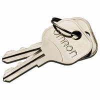
A22K-K
Description
REPLACEMENT KEY A22 SERIES 2 PCS
Manufacturer
Omron
Type
Pushbutton Switchr
Specifications of A22K-K
Accessory Type
Replacement Key
Termination Style
Crimp
For Use With/related Products
A22K Series
For Use With
A22K-3MC-20 - SWITCH KEYLOCK 3POS ALT DPST-NOA22K-3MC-10 - SWITCH KEYLOCK 3POS ALT SPST-NOA22K-3MC-02 - SWITCH KEYLOCK 3POS ALT DPST-NCA22K-3MC-01 - SWITCH KEYLOCK 3POS ALT SPST-NCA22K-3AC-20 - SWITCH KEYLOCK 3POS MOM DPST-NOA22K-3AC-10 - SWITCH KEYLOCK 3POS MOM SPST-NOA22K-3AC-02 - SWITCH KEYLOCK 3POS MOM DPST-NCA22K-2ML-20 - SWITCH KEYLOCK 2POS ALT DPST-NOA22K-2ML-11 - SWITCH KEYLOC 2POS ALT DPST-NO/CA22K-2ML-02 - SWITCH KEYLOCK 2POS ALT DPST-NCA22K-2ML-01 - SWITCH KEYLOCK 2POS ALT SPST-NCA22K-2M-20 - SWITCH KEYLOCK 2POS ALT DPST-NOA22K-2M-11 - SWITCH KEYLOC 2POS ALT SPST-NO/CA22K-2M-02 - SWITCH KEYLOCK 2POS ALT DPST-NCA22K-2M-01 - SWITCH KEYLOCK 2POS ALT SPST-NCA22K-2AL-20 - SWITCH KEYLOCK 2POS MOM DPST-NOA22K-2AL-11 - SWITCH KEYLOC 2POS MOM SPST-NO/CA22K-2AL-02 - SWITCH KEYLOCK 2POS MOM DPST-NCA22K-2AL-01 - SWITCH KEYLOCK 2POS MOM SPST-NCA22K-3ML - SWITCH UNIT KEYLOCK ALT 3POS BLKA22K-3MC - SWITCH UNIT KEYLOCK ALT 3POS BLKA22K-3M - SWITCH UNIT KEYLOCK ALT 3POS BLKA22K-3AC - SWITCH UNIT KEYLOCK MOM 3POS BLKA22K-2ML - SWITCH UNIT KEYLOCK ALT 2POS BLKA22K-2M - SWITCH UNIT KEYLOCK ALT 2POS BLKA22K-2AL - SWITCH UNIT KEYLOCK MOM 2POS BLKZ1536 - SWITCH KEY 3-POS SPST-NO/NC BLKZ1535 - SWITCH KEY 3-POS SPST-NO/NC BLKZ1534 - SWITCH KEY 3-POS SPST-NO/NC BLKZ1533 - SWITCH KEY 3-POS SPST-NO/NC BLKZ1532 - SWITCH KEY 2POS SPST-NO BLACKZ1531 - SWITCH KEY 2POS SPST-NO BLACKZ1530 - SWITCH KEY 2POS SPST-NO BLACK
Lead Free Status / RoHS Status
Lead free / RoHS Compliant
Other names
A22K-K
A22KK
Z1669
A22KK
Z1669


A3P
Precautions
Refer to the Common Precautions for Pushbutton Switches on
page 14.
Correct Use
Mounting
Always make sure that the power is turned OFF before mounting,
removing, or wiring the Switch, or performing maintenance.
After wiring the Switch, make sure that there is a suitable isolation
distance.
Wiring
Perform soldering promptly and correctly at 60 W maximum and
within 3 seconds. (Dip soldering temperature 280_C max.) Wait for
one minute after soldering before exerting any external force on the
solder.
Operating Environment
Do not use in locations that are subject to dust, oil, or metal filings as
these may penetrate the interior of the Switch and cause malfunc-
tion.
LED (for VDC)
Check the terminal polarity when wiring.
The rated voltage is shown on the plate on the back of the lighting
unit, so be sure to use within the voltage shown.
An LED current-limiting resistor is built in, so there is no need to
mount an external resistor.
Incandescent Lamp
Apply 80% of the rated voltage (operating voltage) to the incandes-
cent lamp to improve life expectancy and incandescence.
Character Plate (Character Film)
If preparing the character plate separately, use a heat-resistant film
with a thickness of 0.1 to 0.3 mm.
Do not apply a voltage higher than the maximum rated operat-
ing voltage between the lamp terminals, as there is a risk that
the incandescent lamp or LED will be damaged, and the Push-
button will be ejected.
When replacing the incandescent lamp, first turn OFF the
power supply, and then wait 10 minutes before performing re-
placement, as the lamp is still hot immediately after the power
is turned OFF, so there is a risk of burns.
!
Caution
24.8
–0.3
+0.
dia.
23±0.1 dia.
Using Microloads
Using a standard load switch when a microload circuit is opened or
closed may cause wear on the contacts. Use the switch within the
operating range. (Refer to the diagram below.) Even when using mi-
croload models within the operating range shown below, if inrush
current occurs when the contact is opened or closed, it may cause
the contact surface to become rough, and so decrease life expec-
tancy. Therefore, insert a contact protection circuit where neces-
sary. The minimum applicable load is the N-level reference value.
This value indicates the malfunction reference level for the reliability
level of 60% (λ 60) (conforming to JIS C5003). The equation, λ 60 =
0.5 x 10
than 1/2,000,000 with a reliability level of 60%.
Others
If the panel is to be finished (e.g., coated), make sure that the panel
meets the specified dimensions after the coating.
–4
/time indicates that the estimated malfunction rate is less
Invalid
area
Microload
area
Current (mA)
Standard
load area
A3P
245
Related parts for A22K-K
Image
Part Number
Description
Manufacturer
Datasheet
Request
R

Part Number:
Description:
SWITCH KEY 2POS SPST-NO BLACK
Manufacturer:
Omron
Datasheet:

Part Number:
Description:
SWITCH KEYLOCK 2POS MOM SPST-NC
Manufacturer:
Omron
Datasheet:
Part Number:
Description:
SWITCH KEYLOCK 2POS ALT SPST-NC
Manufacturer:
Omron
Datasheet:
Part Number:
Description:
SWITCH KEYLOCK 2POS ALT SPST-NC
Manufacturer:
Omron
Datasheet:

Part Number:
Description:
SWITCH KEY 3-POS SPST-NO/NC BLK
Manufacturer:
Omron
Datasheet:
Part Number:
Description:
SWITCH KEYLOCK 3POS ALT DPST-NO
Manufacturer:
Omron
Datasheet:
Part Number:
Description:
SWITCH KEYLOCK 2POS MOM DPST-NC
Manufacturer:
Omron
Datasheet:

Part Number:
Description:
SWITCH KEYLOC 2POS MOM SPST-NO/C
Manufacturer:
Omron
Datasheet:
Part Number:
Description:
SWITCH KEYLOCK 2POS MOM DPST-NO
Manufacturer:
Omron
Datasheet:
Part Number:
Description:
SWITCH KEYLOCK 2POS ALT DPST-NC
Manufacturer:
Omron
Datasheet:
Part Number:
Description:
SWITCH PB RND MOM SPST-NO/NC RED
Manufacturer:
Omron
Datasheet:

Part Number:
Description:
SWITCH PB ROUND ALT SPST-NO BLUE
Manufacturer:
Omron
Datasheet:

Part Number:
Description:
SWITCH PB ROUND ALT SPST-NO BLK
Manufacturer:
Omron
Datasheet:

Part Number:
Description:
SWITCH PB ROUND ALT SPST-NO GRN
Manufacturer:
Omron
Datasheet:

Part Number:
Description:
SWITCH PB ROUND ALT SPST-NO RED
Manufacturer:
Omron
Datasheet: