A22K-K Omron, A22K-K Datasheet - Page 30
A22K-K
Manufacturer Part Number
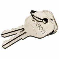
A22K-K
Description
REPLACEMENT KEY A22 SERIES 2 PCS
Manufacturer
Omron
Type
Pushbutton Switchr
Specifications of A22K-K
Accessory Type
Replacement Key
Termination Style
Crimp
For Use With/related Products
A22K Series
For Use With
A22K-3MC-20 - SWITCH KEYLOCK 3POS ALT DPST-NOA22K-3MC-10 - SWITCH KEYLOCK 3POS ALT SPST-NOA22K-3MC-02 - SWITCH KEYLOCK 3POS ALT DPST-NCA22K-3MC-01 - SWITCH KEYLOCK 3POS ALT SPST-NCA22K-3AC-20 - SWITCH KEYLOCK 3POS MOM DPST-NOA22K-3AC-10 - SWITCH KEYLOCK 3POS MOM SPST-NOA22K-3AC-02 - SWITCH KEYLOCK 3POS MOM DPST-NCA22K-2ML-20 - SWITCH KEYLOCK 2POS ALT DPST-NOA22K-2ML-11 - SWITCH KEYLOC 2POS ALT DPST-NO/CA22K-2ML-02 - SWITCH KEYLOCK 2POS ALT DPST-NCA22K-2ML-01 - SWITCH KEYLOCK 2POS ALT SPST-NCA22K-2M-20 - SWITCH KEYLOCK 2POS ALT DPST-NOA22K-2M-11 - SWITCH KEYLOC 2POS ALT SPST-NO/CA22K-2M-02 - SWITCH KEYLOCK 2POS ALT DPST-NCA22K-2M-01 - SWITCH KEYLOCK 2POS ALT SPST-NCA22K-2AL-20 - SWITCH KEYLOCK 2POS MOM DPST-NOA22K-2AL-11 - SWITCH KEYLOC 2POS MOM SPST-NO/CA22K-2AL-02 - SWITCH KEYLOCK 2POS MOM DPST-NCA22K-2AL-01 - SWITCH KEYLOCK 2POS MOM SPST-NCA22K-3ML - SWITCH UNIT KEYLOCK ALT 3POS BLKA22K-3MC - SWITCH UNIT KEYLOCK ALT 3POS BLKA22K-3M - SWITCH UNIT KEYLOCK ALT 3POS BLKA22K-3AC - SWITCH UNIT KEYLOCK MOM 3POS BLKA22K-2ML - SWITCH UNIT KEYLOCK ALT 2POS BLKA22K-2M - SWITCH UNIT KEYLOCK ALT 2POS BLKA22K-2AL - SWITCH UNIT KEYLOCK MOM 2POS BLKZ1536 - SWITCH KEY 3-POS SPST-NO/NC BLKZ1535 - SWITCH KEY 3-POS SPST-NO/NC BLKZ1534 - SWITCH KEY 3-POS SPST-NO/NC BLKZ1533 - SWITCH KEY 3-POS SPST-NO/NC BLKZ1532 - SWITCH KEY 2POS SPST-NO BLACKZ1531 - SWITCH KEY 2POS SPST-NO BLACKZ1530 - SWITCH KEY 2POS SPST-NO BLACK
Lead Free Status / RoHS Status
Lead free / RoHS Compliant
Other names
A22K-K
A22KK
Z1669
A22KK
Z1669


A3D
Precautions
Refer to the Common Precautions for Pushbutton Switches on
page 14.
Correct Use
Mounting
Always make sure that the power is turned OFF before mounting,
removing, or wiring the Switch, or performing maintenance.
Do not tighten the mounting ring excessively using pliers or a similar
tool. Excessive tightening may damage the mounting ring. (Tighten-
ing torque: 0.20 to 0.29 N⋅m)
Wiring
When wiring, use wires of a size appropriate for the applied voltage
and carry current. Perform soldering correctly under the conditions
given below. Using the Switch with the wires soldered incorrectly
may cause the terminals to become abnormally hot and cause a fire.
Wait for one minute after soldering before exerting any external
force on the solder.
Use a non-corrosive rosin liquid for the flux.
Perform wiring so that the wire sheaths do not come into contact
with the Switch. If this is unavoidable, use wires that can withstand
temperatures of 100°C min.
After wiring to the Switch has been completed, ensure an appropri-
ate insulation distance.
LED
The polarity of the LED is indicated on the back of the Switch. Wire
the LED correctly according to the polarity.
The built-in LED does not have a limiting resistor. Connect a limiting
resistor.
Make sure that the limiting resistor satisfies the characteristics of
the built-in LED. The forward current of the built-in LED must be
8 mA minimum.
The resistance can be calculated by using the following expression.
Recommended Values for Limiting Resistance
Note: The above values are calculated values that can be used as
28
Cat. No. A031-E1-05
5 VDC
12 VDC
24 VDC
1. Hand soldering: At 30 W within 5 seconds.
2. Dip soldering: At 240°C within 3 seconds.
R = (E –V
E:
V
I
Voltage
F
F
:
: LED forward voltage (V)
reference.
Operating voltage (V)
LED forward current (A)
F
)/I
F
165 Ω
515 Ω
1,100 Ω
(Ω)
ALL DIMENSIONS SHOWN ARE IN MILLIMETERS.
To convert millimeters into inches, multiply by 0.03937. To convert grams into ounces, multiply by 0.03527.
Red
140 Ω
490 Ω
1,090 Ω
(White)
Yellow
145 Ω
495 Ω
1,095 Ω
Green
Calculation Example for Limiting Resistance
Conditions: Red LED with an I
From the red LED characteristic given previously, V
when I
Thus the recommended resistance is 1.1 kΩ at 1 W (2 x I
note)
Note: A factor of 2 is applied because the permissible wattage of
Operating Environment
Ensure that dust, metal powder, or oil do not enter the interior of the
Switch.
Using Microloads
Using a standard load switch for opening and closing a microload
circuit may cause wear on the contacts. Use the switch within the
operating range. (Refer to the diagram below.) Even when using mi-
croload models within the operating range shown below, if inrush
current occurs when the contact is opened or closed, it may cause
the contact surface to become rough, and so decrease life expec-
tancy. Therefore, insert a contact protection circuit where neces-
sary. The minimum applicable load is the N-level reference value.
This value indicates the malfunction reference level for the reliability
level of 60% (λ 60) (conforming to JIS C5003). The equation, λ 60 =
0.5 x 10
than 1/2,000,000 with a reliability level of 60%.
F
–4
the resistor must be twice as large as the required wattage.
is 20 mA. Therefore, R = (24 V – 1.7 V)/0.02 A = 1,100 Ω.
/times indicates that the estimated malfunction rate is less
Invalid
area
Microload
area
F
of 20 mA at 24 V and a Ta of 25°C.
Current (mA)
Standard
load area
F
will be 1.7 V
F
2
R). (see
A3D
Related parts for A22K-K
Image
Part Number
Description
Manufacturer
Datasheet
Request
R

Part Number:
Description:
SWITCH KEY 2POS SPST-NO BLACK
Manufacturer:
Omron
Datasheet:

Part Number:
Description:
SWITCH KEYLOCK 2POS MOM SPST-NC
Manufacturer:
Omron
Datasheet:
Part Number:
Description:
SWITCH KEYLOCK 2POS ALT SPST-NC
Manufacturer:
Omron
Datasheet:
Part Number:
Description:
SWITCH KEYLOCK 2POS ALT SPST-NC
Manufacturer:
Omron
Datasheet:

Part Number:
Description:
SWITCH KEY 3-POS SPST-NO/NC BLK
Manufacturer:
Omron
Datasheet:
Part Number:
Description:
SWITCH KEYLOCK 3POS ALT DPST-NO
Manufacturer:
Omron
Datasheet:
Part Number:
Description:
SWITCH KEYLOCK 2POS MOM DPST-NC
Manufacturer:
Omron
Datasheet:

Part Number:
Description:
SWITCH KEYLOC 2POS MOM SPST-NO/C
Manufacturer:
Omron
Datasheet:
Part Number:
Description:
SWITCH KEYLOCK 2POS MOM DPST-NO
Manufacturer:
Omron
Datasheet:
Part Number:
Description:
SWITCH KEYLOCK 2POS ALT DPST-NC
Manufacturer:
Omron
Datasheet:
Part Number:
Description:
SWITCH PB RND MOM SPST-NO/NC RED
Manufacturer:
Omron
Datasheet:

Part Number:
Description:
SWITCH PB ROUND ALT SPST-NO BLUE
Manufacturer:
Omron
Datasheet:

Part Number:
Description:
SWITCH PB ROUND ALT SPST-NO BLK
Manufacturer:
Omron
Datasheet:

Part Number:
Description:
SWITCH PB ROUND ALT SPST-NO GRN
Manufacturer:
Omron
Datasheet:

Part Number:
Description:
SWITCH PB ROUND ALT SPST-NO RED
Manufacturer:
Omron
Datasheet: