WLD3-TS Omron, WLD3-TS Datasheet - Page 20
WLD3-TS
Manufacturer Part Number
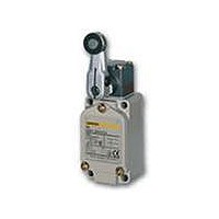
WLD3-TS
Description
SWTCH LMT DPST 6A TOP BALL PLNGR
Manufacturer
Omron
Series
WLr
Datasheet
1.WL_COVER.pdf
(43 pages)
Specifications of WLD3-TS
Circuit
SPDT-DM/DB
Switch Function
On-Mom
Contact Rating @ Voltage
10A @ 125VAC
Actuator Type
Round (Pin Plunger)
Mounting Type
Chassis Mount
Termination Style
Screw Terminal
Operating Force
2720gf
Lead Free Status / RoHS Status
Lead free / RoHS Compliant
Other names
WLD3TS


Ratings
Standard-load Switches
* For high-sensitivity
Approved Standard Ratings
UL/CSA
Standard-load Switches: A600, NEMA
Microload Switches
0.1 A 125 VAC, 0.1 A 30 VDC
TÜV
Note: As an example, AC-15: 2 A/250 V means the following:
Inrush
cur-
rent
Model
Basic models,
overtravel
models (except
for high-
sensitivity
models), and
high-precision
models
High-sensitivity
overtravel
models
WL@
WL01@
WL@-LE
WL01@-LE
WL@-LD
WL01@-LD
Application category
Rated operating current (Ie)
Rated operating voltage (Ue)
Model
WL-LE
WL-LD
overtravel models.
120 VAC
240 VAC
480 VAC
600 VAC
voltage
Indicator-equipped Switches
Rated
Model
General-purpose/Weather-proof Switches
(EN60947-5-1) (Only models with ground terminals are approved.)
Minimum applicable load
NC
NO
Neon
lamp
LED
Item
Carry cur-
Item
30 A max.
(15 A max. *)
20 A max.
(10 A max. *)
AC-15: 2 A/250 V
DC-12: 2 A/48 V
AC-14: 0.1 A/125V
DC-12: 0.1 A/48 V
AC-15: 2 A/250 V
AC-14: 0.1 A/125 V
AC-15: 2 A/115 V
DC-12: 2 A/48 V
AC-14: 0.1 A/115 V
DC-12: 0.1 A/48 V
10 A
Application category
rent
125 VAC
250 VAC
500 VAC
8 VDC
14 VDC
30 VDC
125 VDC
250 VDC
125 VAC
250 VAC
125 VDC
250 VDC
voltage
Rated
and ratings
Max. rated voltage (V)
(V)
10 to 24 AC/DC
115 AC/DC
Make
Note: 1. The above figures are for steady-state
125 AC
250 AC
60
30
15
12
Non-inductive load (A)
Resistive
NC
Current (A)
load
0.8
0.4
0.4
0.2
10
10
10
10
10
2. Inductive loads have a power factor of 0.4 min.
3. A lamp load has an inrush current of 10
4. A motor load has an inrush current of 6
5. For PC loads, use the microload models.
6
5
5
AC-15
2A
250V
NO
currents.
(AC) and a time constant of 7 ms max. (DC).
times the steady-state current.
times the steady-state current.
Break
Thermal cur-
1.5
1.2
NC
1.5
0.2
0.1
6
3
3
2
6
6
4
rent (I
Lamp
load
—
—
0.5 A
0.5 A
0.5 A
10 A
10 A
10 A
NO
1.5
0.8
0.2
0.1
1
3
3
3
5 VDC 160 mA
Leakage current (mA)
the
)
Volt-amperes (VA)
Make
7,200
Inductive
NC
Inductive load (A)
Approx. 0.6
Approx. 1.9
Approx. 0.5
Approx. 0.4
load
0.8
0.4
10
10
10
10
—
—
3
6
NO
Neon lamp
Neon lamp
Indicator
LED
LED
—
—
NC
1.5
Break
5
3
Motor
720
load
0.2
0.1
—
—
6
6
4
NO
2.5
1.5
0.8
Microload Switches
Operation in the following ranges will produce optimum performance.
Characteristics
Note: 1. The above figures are initial values.
*1. The values are calculated at an operating temperature of +5°C to +35°C and an
*2. Durability is 10,000,000 operations min. for general-purpose or high-
*3. Durability is 500,000 operations min. for high-sensitivity models. All
*4. Except flexible rod models. The shock resistance (malfunction) for
*5. For low-temperature models this is –40°C to +40°C (with no icing). For heat-
*6. For microload models, the contact resistance is 50 mΩ max. (initial value for
Degree of protection
Durability
*1
Operating speed
Operating
frequency
Rated frequency
Insulation resistance
Contact resistance
Dielectric
strength
Rated insulation voltage (Ui)
Pollution degree (operating
environment)
Short-circuit protective device (SCPD)
Conditional short-circuit current
Conventional enclosed thermal
current (Ithe)
Protection against electric shock Class I
Vibration
resistance
Shock
resistance
Ambient operating temperature
Ambient operating humidity
Weight
operating humidity of 40% to 70%RH. Contact your OMRON sales
representative for more detailed information on other operating environments.
sensitivity overtravel models, and for flexible rod models.
500,000 operations min. for weather-proof models.
microload models are 1,000,000 operations min.
500,000 operations min. for weather-proof models.
microload models is 200 m/s
resistant models the range is +5°C to +120°C.
built-in switch).
Recommended load range
Recommended load range
2. The figures in parentheses for dielectric strength are those for the high-
sensitivity overtravel models.
Rated voltage (V)
30
10
Mechanical
Electrical
Mechanical
Electrical
Between terminals
of the same polarity
Between current-
carrying metal part
and ground
Between each termi-
nal and non-current-
carrying metal part
Malfunction
Destruction
Malfunction
5
1
AC 125
0.1 0.16
DC 30
(Refer to these ratings before using the product.)
1
5 mW
2
min.
5 10
IP67
15,000,000 operations min. *2
750,000 operations min. *3
1 mm/s to 1 m/s (in case of WLCA2)
120 operations/minute min.
30 operations/minute min.
50/60 Hz
100 MΩ min. (at 500 VDC)
25 mΩ max. (initial value for the built-in
switch when tested alone) *6
1,000 VAC (600 VAC), 50/60 Hz for
1 min
2,200 VAC (1,500 VAC), 50/60 Hz for
1 min/Uimp 2.5 kV
2,200 VAC (1,500 VAC), 50/60 Hz for
1 min/Uimp 2.5 kV
250 V (EN60947-5-1)
3 (EN60947-5-1)
10 A, fuse type gG or gI (IEC60269)
100 A (EN60947-5-1)
10 A, 0.5 A (EN60947-5-1)
10 to 55 Hz, 1.5-mm double amplitude *4
1,000 m/s
300 m/s
–10°C to +80°C (with no icing) *5
35% to 95% RH
Approx. 275 g (in case of WLCA2)
Rated current (A) - Resistive load
2
0.8 W
min. *4
100
2
min.
0.5 to 100 mA
5 to 30 VDC
5 VDC 1 mA
Current (mA)
WL/WLM
0.1
20
Related parts for WLD3-TS
Image
Part Number
Description
Manufacturer
Datasheet
Request
R

Part Number:
Description:
SWTCH LMT DPST 6A TOP BALL PLNGR
Manufacturer:
Omron
Datasheet:
Part Number:
Description:
SWTCH LMT DPST 6A TOP BALL PLNGR
Manufacturer:
Omron
Datasheet:
Part Number:
Description:
LS BALL PLUNGER
Manufacturer:
Omron
Datasheet:
Part Number:
Description:
Basic / Snap Action / Limit Switches Limit Switch
Manufacturer:
Omron

Part Number:
Description:
SWITCH LIMIT ROLL W/OVRTRAVL 10A
Manufacturer:
Omron
Datasheet:

Part Number:
Description:
SWITCH LIMIT ADJ ROLL LEVER 10A
Manufacturer:
Omron
Datasheet:
Part Number:
Description:
SWITCH LIMIT ADJ ROLL W/OVTRAVEL
Manufacturer:
Omron
Datasheet:
Part Number:
Description:
SWITCH LIMIT ROLL LEVER SPDT 10A
Manufacturer:
Omron
Datasheet:

Part Number:
Description:
SW LIMIT ADJ ROD LVR SPDT 10A
Manufacturer:
Omron
Datasheet:
Part Number:
Description:
SWITCH LIMIT DPST 6A W/O LEVER
Manufacturer:
Omron
Datasheet:
Part Number:
Description:
SWITCH LIMIT DPST 6A FLEXIBL ROD
Manufacturer:
Omron
Datasheet:
Part Number:
Description:
SWITCH LIMT DPST 6A ADJ ROL LEVR
Manufacturer:
Omron
Datasheet:
Part Number:
Description:
SWITCH LIMIT DPST 6A ROLLR LEVER
Manufacturer:
Omron
Datasheet:
Part Number:
Description:
SWITCH LIMIT DPST 6A ROLLR LEVER
Manufacturer:
Omron
Datasheet: