EA STARTEDIP320J ELECTRONIC ASSEMBLY, EA STARTEDIP320J Datasheet - Page 19
EA STARTEDIP320J
Manufacturer Part Number
EA STARTEDIP320J
Description
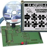
LCD Graphic Display Modules & Accessories Starter/Demoboard w/Touch USB prog
Manufacturer
ELECTRONIC ASSEMBLY
Datasheet
1.EA_STARTEDIP320J.pdf
(25 pages)
Specifications of EA STARTEDIP320J
Pixel Density
320 x 240
Fluid Type
FSTN Positive
Module Size (w X H X T)
121 mm x 92.6 mm x 11.6 mm
Viewing Area (w X H)
115.18 mm x 86.38 mm
Backlighting
Black / White
Background Color
White
Operating Temperature Range
- 20 C to + 70 C
Attached Touch Screen
Yes
Interface
RS-232, I2C BUS, or SPI BUS
Lead Free Status / RoHS Status
Lead free / RoHS Compliant


Specifications may be changed without
prior notice. Printing error reserved
TOP VIEW AFTER 180° ROTATION
The best way to view the EA eDIP320 is diagonally from below (bottom view, 6 o’clock).
The eDIP320 can be installed rotated by 180° to get the top view (12 o’clock).
To correct the contents of the screen, three solder straps (JS, JS1 and JC) have to be resoldered.
POWER-DOWN MODE
To save energy (battery operation), you can activate power-down mode by means of the command
‘ESC PD n1’ (see page 15 below). The LED illumination is switched off, and the contents of the
display become invisible although they are still there.
In power-down mode including suppressor diodes, the eDIP20 typically requires 150 µA.
Thanks to the integrated suppressor diodes, however, the shunt current can also be 1000 µA and
more.
The suppressor diodes can be deactivated by opening the solder straps J1 and J3. Then power-
down current of typically 20 µA is reached.
Important: When the solder straps J1 and J3 are open, it is essential that the polarity of the display
is correct at all the time: VDD, GND (pin 1 + 2). Even very brief polarity reversal or overvoltage can
damage the display immediately and irreparably.
The eDIP320 can be woken from power-down mode by a level of L at pin 13 (WUP), when the
screen is touched or through the I2C address.
Bottom View
Important: Always place all solder straps in the
same position and desolder them cleanly. Short
circuits destroy the eDIP320-8.
If an eDIP320-8 with a touch panel is used, the
touch interpretation must also be changed with the
command ‘ESC AO 1’.
EA eDIP320-8
Top View
Page 19
Related parts for EA STARTEDIP320J
Image
Part Number
Description
Manufacturer
Datasheet
Request
R

Part Number:
Description:
Display Modules & Development Tools Starter/Demoboard Windows USB For DOGM
Manufacturer:
ELECTRONIC ASSEMBLY

Part Number:
Description:
Display Modules & Development Tools Starter/Demoboard DOGM/ Windows USB
Manufacturer:
ELECTRONIC ASSEMBLY
Datasheet:

Part Number:
Description:
LCD Character Display Modules 4x20 Yellow/Green RS-232 Interface
Manufacturer:
ELECTRONIC ASSEMBLY
Part Number:
Description:
LCD Character Display Modules 4x20 Blue-White RS-232 Interface
Manufacturer:
ELECTRONIC ASSEMBLY
Part Number:
Description:
LCD Character Display Modules 2x16 Yellow/Green RS-232 Interface
Manufacturer:
ELECTRONIC ASSEMBLY

Part Number:
Description:
LCD Character Display Modules STN(+) Reflective Yel/Grn Background
Manufacturer:
ELECTRONIC ASSEMBLY
Datasheet:

Part Number:
Description:
LCD Character Display Modules STN(-) Transmissive Blue Background
Manufacturer:
ELECTRONIC ASSEMBLY
Datasheet:

Part Number:
Description:
LCD Character Display Modules FSTN(-) Transmissive Black Background
Manufacturer:
ELECTRONIC ASSEMBLY
Datasheet:

Part Number:
Description:
LCD Character Display Modules Yel/Green Contrast Yl/Grn LED Backlight
Manufacturer:
ELECTRONIC ASSEMBLY
Datasheet:

Part Number:
Description:
LCD Character Display Modules STN(+) Transmissive Yel/Grn Background
Manufacturer:
ELECTRONIC ASSEMBLY
Datasheet:

Part Number:
Description:
LCD Touch Panels Touchpanel Analog for DOGM128-6
Manufacturer:
ELECTRONIC ASSEMBLY
Datasheet:
Part Number:
Description:
LCD Touch Panels Touchpanel Analog For DOGS102
Manufacturer:
ELECTRONIC ASSEMBLY
Datasheet:
Part Number:
Description:
LCD Touch Panels Touchpanel Analog For DOGXL160
Manufacturer:
ELECTRONIC ASSEMBLY
Datasheet:
Part Number:
Description:
LCD Touch Panels Touchpanel Analog For DOG-L128-6
Manufacturer:
ELECTRONIC ASSEMBLY
Datasheet:

Part Number:
Description:
LED Displays Bezel 017-xx Series 75.0x24.2/ 91.0x36.4
Manufacturer:
ELECTRONIC ASSEMBLY
Datasheet: