NTE3041 NTE ELECTRONICS, NTE3041 Datasheet
NTE3041
Specifications of NTE3041
Available stocks


Related parts for NTE3041


NTE3041 Summary of contents
Page 1
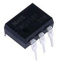
... Description: The NTE3041 is an optoisolator in a 6–Lead DIP type package consisting of a gallium arsenide in- frared emitting diode optically coupled to a monolithic silicon phototransistor detector. Features: D High Current Transfer Ratio: 100% Min @ Spec Conditions D Guaranteed Switching Speeds Applications: D General Purpose Switching Circuits ...
Page 2
Electrical Characteristics: (T Parameter Input LED Forward Voltage Reverse Leakage Current Capacitance Output Transistor Collector–Emitter Dark Current Collector–Base Dark Current Collector–Emitter Breakdown Voltage Collector–Base Breakdown Voltage Emitter–Base Breakdown Voltage DC Current Gain Collector–Emitter Capacitance Collector–Base Capacitance Emitter–Base Capacitance Coupled Output ...
Page 3
Anode Cathode N. .070 (1.78) Max .350 (8.89) Max .200 (5.08) Max .085 (2.16) Max Pin Connection Diagram Base Collector 3 4 Emitter 5 4 .260 (6.6) Max 2 3 .350 (8.89) Max .100 ...