E3S-CR11 Omron, E3S-CR11 Datasheet
E3S-CR11
Specifications of E3S-CR11
Available stocks


Related parts for E3S-CR11


E3S-CR11 Summary of contents
Page 1
... Connector type Cable size 3-wire DC 22 AWG R R MicroChange 2 Part number Sensing distance g Pre-leaded 30 m (98.43 ft) E3S-CT11 3 m (9.84 ft) E3S-CR11 70 cm (27.56 in) E3S-CD11 2 m (6.56 ft) E3S-CD12 30 m (98.43 ft) E3S-CT61 3 m (9.84 ft) E3S-CR61 70 cm (27.56 in) E3S-CD61 2 m (6.56 ft) E3S-CD62 Length Straight connector ...
Page 2
... Mutual interference protection Control output p Type Max. load Residual voltage Response time p OFF ON Circuit protection Vibration Destruction resistance Shock resistance Destruction 2 E3S-CT11 E3S-CR11 E3S-CT61 E3S-CR61 E3S-CT16 E3S-CR16 E3S-CT66 E3S-CR66 Through-beam Polarized retroreflective VDC, 10% ¦ max. (emitter and 40 mA max. receiver 98.43 ft ...
Page 3
... ON when light is received. Dark-ON ON when light is not received. PNP Light-ON ON when light is received. Dark-ON ON when light is not received. E3S-CT11 E3S-CR11 E3S-CT61 E3S-CR61 E3S-CT16 E3S-CR16 E3S-CT66 E3S-CR66 Stability indicator (green), Light Incident (red) y Power ON (red) Stability indicator (green), Light Incident (red) Acrylic ...
Page 4
... Detecting distance X (m) 4 E3S-CRj6 (E39-R1 Reflector) Distance (m) Operating Range (Typical) E3S-CDj6 (Left and Right) Set distance x (cm) Sensing object Y X Detecting distance X (cm) E3S-C E3S-CDj6 Distance (cm) E3S-CDj7 and E3S-CDj2 (Left and Right) Set distance x (cm) Sensing object Y X Detecting distance X (cm) ...
Page 5
... Sensing object: White paper OFF ON Size of object (cm) J REFLECTOR PARALLEL MOVEMENT (TYPICAL) E3S-CRj6 E39-R1 Reflector Y X Set distance X (cm) Detecting distance X (cm) E3S-CDj7 E3S-CDj2 Sensing object: White paper OFF ON Size of object (cm) E3S-CDj7 and E3S-CDj2 (Up and Down) Set distance X (cm) Sensing object Y X E3S-C 5 ...
Page 6
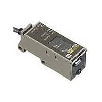
... E3S-C Dimensions Unit: mm (inch) J SENSORS E3S-CT11, E3S-CR11 E3S-CD11, E3S-CD12 Stability indicator (green) Two mounting holes Lens (17 x 11) Receiver** 2.2 (0.09) 20.2 (0.80) 7.7 (0.30) 9.3 (0.37) Optical axis Emitter * The mounting bracket can be attached to side A. 1.5 (0.06) ** For E3S-CT11, optical viewing for the emitter and the receiver are from the top portion of the sensor. ...
Page 7
... The mounting bracket can be attached to side A. ** For E3S-CT61, optical viewing for the emitter and the receiver are from the top portion of the sensor. 57 (2.24) Receiver** 20.8 (0.82) Emitter 4 (0.16) dia. Optical axis 4.2 (0.17) 5 ...
Page 8
... Note.) (0.37) 1.5 (0.06) Note: Mounting bracket can be attached to side A. E3S- -CT66 15.8 (0.62) Lens (17 x 11) Two, Mounting holes Stability indicator Light indicator (receiver) (red) (receiver) (green) Power indicator 2.2 (emitter) (red) 7.2 (0.09) 4 ...
Page 9
... Optical axis Emitter (0.35) 4.2 4.2 5.6 14.4 14.4 (0.57) (0.57) 25.4 (1.00) 31 (1.22) 43.8 (1.72) 23.2 31 (0.91) (1.22) E3S-C 20 (0.79) 20.4 (0.80) Mounting holes 22.2 (0.87) 12 Two, M4 (0.47) 20 4.2 (0.79) (0.17) 25.4 (1.00) Two, M4 29.5 (1.16) 17.3 (0.68 ...
Page 10
... E3S-C J CORNER CUBE REFLECTORS E39-R1 Retroreflector (Included with E3S- CR11/CR61) E39-S61 Slit Kit for E3S-C 10 40.3 (1.59) Two, 3.5 dia. 34 (1.34) 7 62.1 (2.46) 59.9 52 (2.36) (2.05) 8 (0.31) 1.6 (0.06) See note 11 (0.43) 20 (0.79) 6.5 (0.26) 20.1 (0.79) E3S-C 7.5 (0.30) 2.7 (0 ...
Page 11
... Nomenclature J OPERATION PANEL Use the NPN and PNP output selector on the operation panel to select the type of output transistor. Use the Light-ON and Dark-ON selector on the operation panel to select the operation mode of the E3S-C. Horizontal Model Stability indicator (green) Light incident indicator (red) ...
Page 12
... Unlike conventional photoelectric sensors, the variation in the sensitivity among several E3S-C photoelectric sensors is minimal. This means the sensitivity can be adjusted on only a single photoelectric sensor, and then the adjusters on the other E3S-C photoelectric sen- sors can be set to the same scale position. There should be no need to adjust the sensitivity of each photoelectric sensor individually. ...
Page 13
... Either separate the wiring, or use shielded lines as input/output lines to the photoelectric sensor. The cord connected to the E3S-C can be extended up to 100 m pro- vided that the diameter of each wire of the cord is 0 POWER SUPPLY ...
Page 14
... OMRON ELECTRONICS LLC One East Commerce Drive Schaumburg, IL 60173 1-800-55-OMRON Cat. No. CEDSAX4 11/01 OMRON ON- -LINE Global -- http://www.omron.com USA -- http://www.omron.com/oei Canada -- http://www.omron.com/oci Specifications subject to change without notice. E3S-C OMRON CANADA, INC. 885 Milner Avenue Scarborough, Ontario M1B 5V8 416-286-6465 Printed in U.S.A. ...