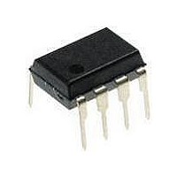
PS9505-AX CEL, PS9505-AX Datasheet

PS9505-AX
Specifications of PS9505-AX
Related parts for PS9505-AX
PS9505-AX Summary of contents
Page 1
... The PS9505, PS9505L1, PS9505L2 and PS9505L3 are optically coupled isolators containing a GaAlAs LED on the input side and a photo diode, a signal processing circuit and a power output transistor on the output side on one chip. The PS9505 Series is designed specifically for high common mode transient immunity (CMR), high output current and high switching speed. ...
Page 2
... Lead Bending Type (Gull-wing) For Surface Mount +0.5 9.25 –0. +0.4 1.01 –0.2 2.54 0.5±0.15 0.25 M R08DS0015EJ0001 Rev.0.01 May 12, 2010 PS9505 7.62 6 15° PS9505L3 5 4 9.65 ±0.4 6.5 0.74±0.25 Chapter Title +0.5 –0.1 +0.5 –0.1 Page ...
Page 3
... Lead Bending Type (Gull-wing) For Long Creepage Distance (Surface Mount) +0.5 9.25 –0. +0.4 1.01 –0.2 2.54 0.5±0.15 0.25 M R08DS0015EJ0001 Rev.0.01 May 12, 2010 PS9505L1 10.16 6 15° PS9505L2 5 4 11.8 ±0.4 6.5 0.9±0.25 Chapter Title +0.5 –0.1 +0.5 –0.1 Page ...
Page 4
... ON OFF L MARKING EXAMPLE No. 1 pin Mark 9505 NT031 Week Assembled Year Assembled (Last 1 Digit) In-house Code Rank Code R08DS0015EJ0001 Rev.0.01 May 12, 2010 PS9505, PS9505L3 PS9505L1, PS9505L2 0.4 mm (Tr. 1) (Tr. 2) SHIELD Tr. 1 Tr. 2 Output ON OFF H OFF ON L Type Number Assembly Lot Chapter Title ...
Page 5
... Preliminary document Specifications in this document are tentative and subject to change. PS9505,PS9505L1,PS9505L2,PS9505L3 ABSOLUTE MAXIMUM RATINGS (T Parameter Diode Forward Current Peak Transient Forward μ Current (Pulse Width < Reverse Voltage High Level Peak Output Detector *1 Current Low Level Peak Output *1 Current Supply Voltage (V Output Voltage ...
Page 6
... Preliminary document Specifications in this document are tentative and subject to change. PS9505,PS9505L1,PS9505L2,PS9505L3 ELECTRICAL CHARACTERISTICS (T = − GND, unless otherwise specified) F (OFF) EE Parameter Diode Forward Voltage Reverse Current Input Capacitance Detector High Level Output Current Low Level Output Current High Level Output Voltage ...
Page 7
... Preliminary document Specifications in this document are tentative and subject to change. PS9505,PS9505L1,PS9505L2,PS9505L3 SWITCHING CHARACTERISTICS (T = − GND, unless otherwise specified) F (OFF) EE Parameter Propagation Delay Time (L → H) Propagation Delay Time (H → L) Pulse Width Distortion (PWD) Propagation Delay Time (Difference Between Any Two Products) ...
Page 8
... Preliminary document Specifications in this document are tentative and subject to change. PS9505,PS9505L1,PS9505L2,PS9505L3 TEST CIRCUIT Fig Test Circuit μ 0 SHIELD Fig Test Circuit μ 0 SHIELD Fig Test Circuit FLH SHIELD R08DS0015EJ0001 Rev.0.01 May 12, 2010 SHIELD 100 mA 4 SHIELD Fig. 6 UVLO Test Circuit 1 μ ...
Page 9
... Preliminary document Specifications in this document are tentative and subject to change. PS9505,PS9505L1,PS9505L2,PS9505L3 Fig 500 Ω kHz 50% DUTY 4 CYCLE SHIELD Fig. 8 CMR Test Circuit and Wave Forms SHIELD Remark CMR Test : Connect pin 1 and pin 4 to the LED common. R08DS0015EJ0001 Rev.0.01 May 12, 2010 ...
Page 10
... Tape Direction Outline and Dimensions (Reel) R 1.0 Packing: 1 000 pcs/reel R08DS0015EJ0001 Rev.0.01 May 12, 2010 +0.1 1.5 –0 10.7±0.1 12.0±0.1 PS9505L2-E3 2.0±0.5 13.0±0.2 21.0±0.8 Chapter Title 4.5 MAX. 4.1 ±0.1 0.3±0.05 2.0±0.5 25.5±1.0 29.5±1.0 23 ...
Page 11
... Tape Direction Outline and Dimensions (Reel) Packing: 1 000 pcs/reel R08DS0015EJ0001 Rev.0.01 May 12, 2010 +0.1 1.5 –0 10.3±0.1 12.0±0.1 PS9505L3-E3 2.0±0.5 13.0±0.2 R 1.0 21.0±0.8 Chapter Title 5.3 MAX. 4.75±0.1 0.35±0.05 2.0±0.5 17.5±1.0 21.5± ...
Page 12
... Specifications in this document are tentative and subject to change. PS9505,PS9505L1,PS9505L2,PS9505L3 RECOMMENDED MOUNT PAD DIMENSIONS (UNIT: mm) Part Number lead bending type (Gull-wing) PS9505L2 for long creepage distance (surface mount) lead bending type (Gull-wing) PS9505L3 for surface mount R08DS0015EJ0001 Rev.0.01 May 12, 2010 A Lead Bending A 10.2 8 ...
Page 13
... Preliminary document Specifications in this document are tentative and subject to change. PS9505,PS9505L1,PS9505L2,PS9505L3 NOTES ON HANDLING 1. Recommended soldering conditions (1) Infrared reflow soldering • Peak reflow temperature • Time of peak reflow temperature • Time of temperature higher than 220°C • Time to preheat temperature from 120 to 180°C • ...
Page 14
... Preliminary document Specifications in this document are tentative and subject to change. PS9505,PS9505L1,PS9505L2,PS9505L3 (4) Cautions • Fluxes Avoid removing the residual flux with freon-based and chlorine-based cleaning solvent. 2. Cautions regarding noise Be aware that when voltage is applied suddenly between the photocoupler’s input and output at startup, the output transistor may enter the on state, even if the voltage is within the absolute maximum ratings ...
Page 15
... Preliminary document Specifications in this document are tentative and subject to change. PS9505,PS9505L1,PS9505L2,PS9505L3 This product uses gallium arsenide (GaAs). Caution GaAs Products GaAs vapor and powder are hazardous to human health if inhaled or ingested, so please observe the following points. • Follow related laws and ordinances when disposing of the product. If there are no applicable laws and/or ordinances, dispose of the product as recommended below ...
Page 16
... Revision History Rev. Date Page − 0.01 May 12, 2010 All trademarks and registered trademarks are the property of their respective owners. PS9505,PS9505L1,PS9505L2,PS9505L3 Preliminary Data Sheet Description First Edition issued Summary ...


