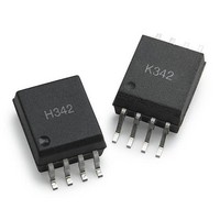
ACPL-K342-060E Avago Technologies US Inc., ACPL-K342-060E Datasheet

ACPL-K342-060E
Specifications of ACPL-K342-060E
Related parts for ACPL-K342-060E
ACPL-K342-060E Summary of contents
Page 1
... IGBT with ratings up to 1200V/150A. For IGBTs with higher ratings, the ACPL-H342/ACPL-K342 can be used to drive a discrete power stage which drives the IGBT gate. The ACPL-H342 and ACPL-K342 have the highest insulation voltage 891Vpeak and 1140Vpeak IORM respectively in the IEC/ EN/DIN EN 60747-5-5 ...
Page 2
... To order, choose a part number from the part number column and combine with the desired option from the option column to form an order entry. Example 1: ACPL-H342-560E to order product of Stretched SO-8 Surface Mount package in Tape and Reel packaging with IEC/EN/ DIN EN 60747-5-5 Safety Approval and RoHS compliant. Example 2: ACPL-K342-000E to order product of Stretched SO-8 Surface Mount package in Tube packaging with UL 5000 V minute and RoHS compliant ...
Page 3
... NOM. 1 ±0.250 0.040 ±0.010 9.7 ±0.25 0.382 ±0.010 ACPL-K342 Outline Drawing 0.381 ±0.13 ª º 0.015 ±0.005 ¬ ¼ 7.62 ª º 0.300 ¬ ¼ 6.807 ±0.127 ª ...
Page 4
... CSA CSA Component Acceptance Notice #5, File CA 88324 IEC/EN/DIN EN 60747-5-5 (ACPL-H342/K342 Option 060 Only) Maximum Working Insulation Voltage Viorm = 891V Table 1. IEC/EN/DIN EN 60747-5-5 Insulation Characteristics* (ACPL-H342 / ACPL-K342 Option 060) Description Installation classification per DIN VDE 0110/1.89, Table 1 for rated mains voltage d 150 V ...
Page 5
... Output IC Power Dissipation Total Power Dissipation Lead Solder Temperature Table 4. Recommended Operating Conditions Parameter Operating Temperature Output Supply Voltage Input Current (ON) Input Voltage (OFF) 5 ACPL-H342 ACPL-K342 Units Conditions 7.0 8.0 mm Measured from input terminals to output terminals, shortest distance through air. 8.0 8.0 mm Measured from input terminals to output terminals, shortest distance path along body ...
Page 6
Table 5. Electrical Specifications (DC) Unless otherwise noted, all typical values are at T fications are at Recommended Operating Conditions ( Ground). EE Parameter Symbol High Level Peak Output Current I OH Low Level ...
Page 7
... I-O 10. Device considered a two-terminal device: pins and 4 shorted together and pins and 8 shorted together. 11. The difference between t and t between any two ACPL-H342 parts under the same test condition. PHL PLH 12. Pins 2 and 4 need to be connected to LED common. 13. Common mode transient immunity in the high state is the maximum tolerable dV will remain in the high state (i.e., V > ...
Page 8
T - TEMPERATURE - °C A Figure 1. High Ouput Rail Voltage vs. Temperature. 0 ...
Page 9
V - OUTPUT LOW VOLTAGE - V OL Figure 1.8 1.6 1.4 1.2 1 0.8 0.6 0.4 0.2 0 -40 -30 -20 -10 0 ...
Page 10
2.0 1.5 1.0 0.5 0.0 -40 -30 -20 - 100 T - TEMPERATURE - °C A Figure ...
Page 11
T PHL 300 T PLH 250 200 150 100 50 0 -40 -30 -20 - 100 T - TEMPERATURE - °C A Figure 19. Propagation delay vs. temperature. 300 ...
Page 12
I = 10mA Figure 23. I test circuit &/$03 CLAMP 4 Figure 24. I test circuit 10mA Figure 25. V test ...
Page 13
V &/$03 CLAMP 4 Figure 27. I test circuit. CLAMP &/$03 CLAMP 4 Figure 28. V test circuit. tCLAMP Figure 29. I test circuit. FLH ...
Page 14
... The gate resistor R and controls the IGBT collector voltage rise and fall times board design, care should be taken to avoid routing the IGBT collector or emitter traces close to the ACPL-H342 input as this can result in unwanted coupling of transient signals into ACPL-H342 and degrade performance. ...
Page 15
... The Miller pin should be connected to V ANODE CATHODE Figure 34. Typical gate driver with output stage in darlington configuration ANODE CATHODE &/$03 CLAMP NC 4 Figure 35. ACPL-H342 with NMOS and PMOS output stage for Rail-to-Rail output voltage OUT 1μ CLAMP Rail-to-Rail Output Figure 34 shows a typical gate driver’s high current output stage with 3 bipolar transistors in darlington con- figuration ...
Page 16
... ≥ I OLPEAK 18V 0V 2.3V = 2.5A = 6.28 The V value of 2.3V in the previous equation is the V OL Step 1: Check the ACPL-H342/K342 power dissipation and increase Rg if necessary. The ACPL-H342/K342 total power dis- sipation ( equal to the sum of the emitter power ( • V • Duty Cycle ...
Page 17
... Anti-Cross Conduction to Prevent Current Shoot Through and Determining Dead Time The ACPL-H342 includes a Propagation Delay Difference (PDD = t high(Q1) and low(Q2) side power transistors from turning on at the same time. This “Anti-Cross” conduction feature prevents large currents from flowing through the power transistors by ensuring t words, the “ ...
Page 18
... The ACPL-H342 with the Anti-Cross feature has a PDD of -10ns and a PDD of -200ns. Since the PDD is always MAX a negative value, the t is always faster than t PHLMAX Thus this simplified the design without having to add any amount of delay for the input LEDs as shown in Figure 39. ...
Page 19
... Under Voltage Lockout The ACPL-H342 Under Voltage Lockout (UVLO) feature is designed to prevent the application of insufficient gate voltage to the IGBT by forcing the ACPL-H342 output low during power-up. IGBTs typically require gate voltages achieve their rated V voltage. At gate voltages CE(ON) ...


