CNY17-4. Vishay, CNY17-4. Datasheet

Transistor Output Optocouplers NPN Phototransistor

CNY17-4.

Manufacturer Part Number
CNY17-4.
Description
Transistor Output Optocouplers NPN Phototransistor
Manufacturer
Vishay
Datasheet

Specifications of CNY17-4.

Forward Current
60 mA
Maximum Fall Time
15 us
Maximum Input Diode Current
60 mA
Maximum Reverse Diode Voltage
6 V
Maximum Rise Time
4.6 us
Output Device
Transistor With Base
Output Type
DC
Configuration
1
Input Type
DC
Maximum Collector Emitter Voltage
70 V
Maximum Collector Emitter Saturation Voltage
400 mV
Isolation Voltage
5300 Vrms
Current Transfer Ratio
320%
Maximum Forward Diode Voltage
1.65 V
Minimum Forward Diode Voltage
1.25 V
Maximum Collector Current
100 mA
Maximum Power Dissipation
150 mW
Maximum Operating Temperature
+ 100 C
Minimum Operating Temperature
- 55 C
Package / Case
PDIP-6
Lead Free Status / RoHS Status
Lead free / RoHS Compliant
CNY17
Vishay Semiconductors
DESCRIPTION
The CNY17 is an optically coupled pair consisting of a
gallium arsenide infrared emitting diode optically coupled to
a silicon NPN phototransitor.
Signal information, including a DC level, can be transmitted
by the device while maintaining a high degree of electrical
isolation between input and output.
The CNY17 can be used to replace relays and transformers
in many digital interface applications, as well as analog
applications such as CRT modulation.
Note
For additional information on the available options refer to option information.
www.vishay.com
214
ORDER INFORMATION
PART
CNY17-1
CNY17-2
CNY17-3
CNY17-4
CNY17-1X006
CNY17-1X007
CNY17-1X009
CNY17-2X006
CNY17-2X007
CNY17-2X009
CNY17-3X006
CNY17-3X007
CNY17-3X009
CNY17-4X006
CNY17-4X007
CNY17-4X009
ABSOLUTE MAXIMUM RATINGS
PARAMETER
INPUT
Reverse voltage
Forward current
Surge current
Power dissipation
Optocoupler, Phototransistor Output, with Base Connection
i179004
NC
A
C
For technical questions, contact: optocoupler.answers@vishay.com
3
1
2
6
5
4
B
C
E
TEST CONDITION
t ≤ 10 µs
FEATURES
• Isolation test voltage 5300 V
• Long term stability
• Industry standard dual-in-line package
• Lead (Pb)-free component
• Component in accordance to RoHS 2002/95/EC
AGENCY APPROVALS
• Underwriters lab file no. E52744 system code H or J
• DIN EN 60747-5-5 (VDE 0884)
• BSI IEC 60950, IEC 60065
• FIMKO
and WEEE 2002/96/EC
CTR 100 % to 200 %, DIP-6 400 mil (option 6)
CTR 160 % to 320 %, DIP-6 400 mil (option 6)
CTR 63 % to 125 %, DIP-6 400 mil (option 6)
CTR 40 % to 80 %, DIP-6 400 mil (option 6)
CTR 100 % to 200 %, SMD-6 (option 7)
CTR 100 % to 200 %, SMD-6 (option 9)
CTR 160 % to 320 %, SMD-6 (option 7)
CTR 160 % to 320 %, SMD-6 (option 9)
CTR 63 % to 125 %, SMD-6 (option 7)
CTR 63 % to 125 %, SMD-6 (option 9)
CTR 40 % to 80 %, SMD-6 (option 7)
CTR 40 % to 80 %, SMD-6 (option 9)
CTR 100 % to 200 %, DIP-6
CTR 160 % to 320 %, DIP-6
CTR 63 % to 125 %, DIP-6
CTR 40 % to 80 %, DIP-6
SYMBOL
P
I
V
FSM
I
diss
F
R
REMARKS
RMS
VALUE
100
2.5
60
6
Document Number: 83606
Rev. 1.6, 10-Dec-05
UNIT
mW
mA
V
A

Related parts for CNY17-4.

CNY17-4. Summary of contents

Page 1

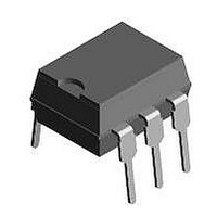
... i179004 DESCRIPTION The CNY17 is an optically coupled pair consisting of a gallium arsenide infrared emitting diode optically coupled to a silicon NPN phototransitor. Signal information, including a DC level, can be transmitted by the device while maintaining a high degree of electrical isolation between input and output. The CNY17 can be used to replace relays and transformers in many digital interface applications, as well as analog applications such as CRT modulation ...

Page 2

... 100 amb T 260 sld MIN. TYP. MAX. V 1. 750 500 th 0.25 0.4 CEsat C 0 CEO CEO I 5 100 CEO I 5 100 CEO www.vishay.com CNY17 UNIT RMS Ω Ω °C °C °C UNIT V V µ 215 ...

Page 3

... Ω Ω Ω Ω CNY17-1 F CNY17 CNY17 CNY17 CNY17-1 F CNY17 CNY17 CNY17 CNY17-1 F CNY17 CNY17 CNY17 CNY17-1 F CNY17 CNY17 CNY17-4 F MIN. TYP. MAX. CTR 40 80 CTR 63 125 CTR 100 200 CTR 160 320 CTR 13 30 CTR 22 45 CTR 34 70 ...

Page 4

... Vishay Semiconductors 1000 ( ° 100 0 (mA) icny17_04 F Fig Current Transfer Ratio vs. Diode Current 1000 ( ° 100 (mA) icny17_05 F Fig Current Transfer Ratio vs. Diode Current 1000 ( ° 100 0 (mA) icny17_06 F Fig Current Transfer Ratio vs. Diode Current www.vishay.com CNY17 217 ...

Page 5

... µ µ µ µ µ (V) icny17_10 CE Fig Output Characteristics 1 °C 50 °C 75 °C 1.1 1.0 0.9 0 (mA) F icny17_11 Fig Forward Voltage (V,T) CEO ( 0 0.01 0.001 °C TA icny17_12 Fig Collector Emitter Off-state Current Document Number: 83606 Rev. 1.6, 10-Dec-05 15 100 100 ...

Page 6

... Fig Saturation Voltage vs. Collector Current and Modulation Depth CNY17-3 Document Number: 83606 For technical questions, contact: optocoupler.answers@vishay.com Rev. 1.6, 10-Dec-05 Optocoupler, Phototransistor Output, with Base Connection 100 Collector Current and Modulation Depth CNY17 100 Fig Permissible Power Dissipation for Transistor and Diode 100 Vishay Semiconductors 1 ...

Page 7

... CNY17 Vishay Semiconductors PACKAGE DIMENSIONS in inches (millimeters) 0.248 (6.30) 0.256 (6.50) 0.039 (1.00) min. 4° typ. 0.018 (0.45) 0.022 (0.55) i178004 Option 6 0.407 (10.36) 0.391 (9.96) 0.307 (7.8) 0.291 (7.4) 0.028 (0.7) 0.014 (0.35) 0.010 (0.25) 0.400 (10.16) 0.430 (10.92) www.vishay.com For technical questions, contact: optocoupler ...

Page 8

... Vishay Semiconductor GmbH, P.O.B. 3535, D-74025 Heilbronn, Germany Document Number: 83606 For technical questions, contact: optocoupler.answers@vishay.com Rev. 1.6, 10-Dec-05 Optocoupler, Phototransistor Output, with Base Connection and may do so without further notice. CNY17 Vishay Semiconductors www.vishay.com 221 ...

Page 9

... Vishay disclaims any and all liability arising out of the use or application of any product described herein or of any information provided herein to the maximum extent permitted by law. The product specifications do not expand or otherwise modify Vishay’ ...

Related keywords