TCDT1120 Vishay, TCDT1120 Datasheet
TCDT1120
Specifications of TCDT1120
Available stocks


Related parts for TCDT1120

TCDT1120 Summary of contents
Page 1
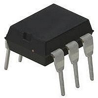
... Optocoupler, Phototransistor Output 17201_6 17201_4 DESCRIPTION The TCDT1120(G) series consists of a phototransistor optically coupled to a gallium arsenide infrared emitting diode lead plastic dual in line package. (1) ORDER INFORMATION PART TCDT1120 TCDT1122 TCDT1123 TCDT1124 TCDT1120G TCDT1122G TCDT1123G TCDT1124G Note ( leadform 10.16 mm not marked on the body. ...
Page 2
... TCDT1120, TCDT1120G Vishay Semiconductors ABSOLUTE MAXIMUM RATINGS PARAMETER INPUT Reverse voltage Forward current Forward surge current Power dissipation Junction temperature OUTPUT Collector emitter voltage Emitter collector voltage Collector current Collector peak current Power dissipation Junction temperature COUPLER Isolation test voltage (RMS) ...
Page 3
... T si SYMBOL = test IOTM test (see figure 500 ≤ 100 °C R amb IO ≤ 150 °C amb R IO optocoupleranswers@vishay.com TCDT1120, TCDT1120G Vishay Semiconductors MIN. TYP. MAX 125 100 200 160 320 MIN. TYP. MAX. 130 265 6 150 MIN. TYP. MAX. 1.6 6 1.3 ...
Page 4
... TCDT1120, TCDT1120G Vishay Semiconductors 300 P (mW) si 250 200 150 100 I (mA 100 125 150 175 200 95 10934 T - Ambeint Temperature(°C) amb Fig Derating Diagram SWITCHING CHARACTERISTICS PARAMETER TEST CONDITION = 100 Ω, (see figure 3) Current time 100 Ω, (see figure 3) Delay time ...
Page 5
... TCDT1123G TCDT1124 t on TCDT1124G TCDT1120 t off TCDT1120G TCDT1123 t off TCDT1123G TCDT1124 t off TCDT1124G off Storage time Fall time + t ) Turn-off time 95 10804 11698 optocoupleranswers@vishay.com TCDT1120, TCDT1120G Vishay Semiconductors MIN. TYP. MAX. 5 16.5 21.5 20 22.5 37 mA; adjusted through C input amplitude = 50 Ω 0. µs ...
Page 6
... TCDT1120, TCDT1120G Vishay Semiconductors + Ω 0. µs p Channel I Channel II 50 Ω 1 kΩ 95 10843 Fig Test Circuit, Saturated Operation 300 Coupled device 250 200 Phototransistor 150 IR-diode 100 Ambient Temperature (°C) 96 11700 amb Fig Total Power Dissipation vs. Ambient Temperature 1000 100 ...
Page 7
... Document Number: 83532 For technical questions, contact: Rev. 1.7, 28-Oct-09 Optocoupler, Phototransistor Output = 100 10 Fig Current Transfer Ratio vs. Forward Current 20 % used 100 Fig Current Transfer Ratio vs. Forward Current 100 10 optocoupleranswers@vishay.com TCDT1120, TCDT1120G Vishay Semiconductors 1000 TCDT1123( 100 Forward Current (mA) 14797 F 1000 TCDT1124(G) ...
Page 8
... TCDT1120, TCDT1120G Vishay Semiconductors 50 TCDT1123(G) saturated operation =1k Ω Forward Current (mA) 14800 F Fig Turn-on/off Time vs. Forward Current 50 TCDT1124(G) saturated operation =1k Ω Forward Current (mA) 14801 F Fig Turn-on/off Time vs. Forward Current 20 TCDT1122(G) non- saturated 15 operation 100 Ω off Collector Current (mA) 14802 C Fig Turn-on/off Time vs. Collector Current www ...
Page 9
... TCDT1122 V YWW 24 21764-39 optocoupleranswers@vishay.com TCDT1120, TCDT1120G Vishay Semiconductors 7.62 typ. 6.5 ± 0.3 7.62 to 9.5 typ. 7.62 typ. 6.5 ± 0.3 10.16 (typ.) www.vishay.com 797 ...
Page 10
... Vishay product could result in personal injury or death. Customers using or selling Vishay products not expressly indicated for use in such applications their own risk and agree to fully indemnify and hold Vishay and its distributors harmless from and against any and all claims, liabilities, expenses and damages arising or resulting in connection with such use or sale, including attorneys fees, even if such claim alleges that Vishay or its distributor was negligent regarding the design or manufacture of the part ...