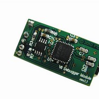
VNC2 DEBUG MODULE FTDI, VNC2 DEBUG MODULE Datasheet - Page 7

VNC2 DEBUG MODULE
Manufacturer Part Number
VNC2 DEBUG MODULE
Description
Interface Modules & Development Tools USB Vinculum-II Debug/Programmer Mod
Manufacturer
FTDI
Datasheet
1.VNC2_DEBUG_MODULE.pdf
(16 pages)
Specifications of VNC2 DEBUG MODULE
Interface Type
USB, Serial, UART, FIFO, SPI
Data Bus Width
Serial, 8 bit
Operating Supply Voltage
5 V
Product
Interface Development Tools
Ic Product Type
Debugger / Programmer
Kit Contents
Miniature Board, USB Connector
Features
Low USB Bandwidth Consumption, Programming And Debugging For VNC2 IC Designs
Svhc
No SVHC (18-Jun-2010)
Rohs Compliant
Yes
Supported Devices
VNC2
For Use With/related Products
VNC2
Lead Free Status / RoHS Status
Lead free / RoHS Compliant
3.2 Components
Table 3.1 Component Descriptions
3.3
Table 3.2 Signal Descriptions
Note: Signal levels on pins 1, 4 and 5 have 3.3V signalling levels to match the VNC2 interface.
Debug Connector
USB Connector
FT232R
2 Port Buffer
Transmit / Receive LED (red)
Power LED (yellow)
FET switch
Debug Interface Description (CN2)
Pin No.
1
2
3
4
5
6
Name
Debug. IF
RESET#
PROG#
Name
[Key]
GND
VCC
Copyright © 2010 Future Technology Devices International Limited
`
Designator
Board
5V Output
CN2
CN1
Output
Output
U1
U3
D1
Type
D2
Q1
PWR
I/O
-
Description
Debug connector, 6-way 2mm pitch female connector.
USB Mini-B type connector for connecting to PC.
FTDI FT232R USB to serial converter device.
2 port buffer device used to convert VNC2 debug signal
from single bit bidirectional signal into separate
transmit and receive signals for FT232R. Data flow
direction control on the buffer is carried out by the
TXEN output from the FT232R. TXEN at logic ‘1’ will
indicate transmit.
LED indicating transmit or receive traffic.
LED indicating power status.
FET switch used to switch power on or off on connector
CN2. FET switch is controlled by PWREN# output from
FT232R.
Debugger Interface.
Not connected.
Module ground supply pin.
Connects to VNC2 RESET# pin. This pin may be
used in combination with PROG# and the UART
interface to program firmware into the VNC2
device.
Connects to VNC2 PROG# pin. This pin is used in
combination with the RESET# pin and the UART
interface to program firmware into the VNC2
device.
5V output to V2DIP module (from USB bus power).
VNC2 Debug Module Datasheet Version 1.0
Description
Document Reference No.: FT_000254
Clearance No.: FTDI# 149
6


