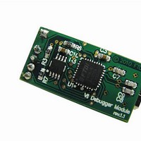
VNC2 DEBUG MODULE FTDI, VNC2 DEBUG MODULE Datasheet - Page 8

VNC2 DEBUG MODULE
Manufacturer Part Number
VNC2 DEBUG MODULE
Description
Interface Modules & Development Tools USB Vinculum-II Debug/Programmer Mod
Manufacturer
FTDI
Datasheet
1.VNC2_DEBUG_MODULE.pdf
(16 pages)
Specifications of VNC2 DEBUG MODULE
Interface Type
USB, Serial, UART, FIFO, SPI
Data Bus Width
Serial, 8 bit
Operating Supply Voltage
5 V
Product
Interface Development Tools
Ic Product Type
Debugger / Programmer
Kit Contents
Miniature Board, USB Connector
Features
Low USB Bandwidth Consumption, Programming And Debugging For VNC2 IC Designs
Svhc
No SVHC (18-Jun-2010)
Rohs Compliant
Yes
Supported Devices
VNC2
For Use With/related Products
VNC2
Lead Free Status / RoHS Status
Lead free / RoHS Compliant
Document Reference No.: FT_000254
VNC2 Debug Module Datasheet Version 1.0
Clearance No.: FTDI# 149
`
3.4 Connecting Debug Module on V2DIPx-x Modules
The V2DIPx-x modules have a compatible 6-pin, 2mm pitch male connector for directly connecting the
VNC2 debug module to the V2DIPx-x board.
Figure 3.2 Example Connection of Debug Module Connection to V2DIP2-64
3.5 Connecting Debug Module on Custom PCB
Where a customer is developing their own VNC2 based hardware, customers can support the VNC2 debug
module connectivity by hosting a compatible connector on their PCB. The VNC2 debug module requires a
6-pin, 2mm pitch male connector providing connectivity to the VNC2 debug pin, PROG# and RESET# pins,
as well as GND and VCC pins. Details on the required connectivity are shown on
Figure 3.3.
A Samtec connector, part number TMM-106-01-G-S-RA, has been used as the mating male connector for
the debug module on the V2DIPx-x modules. Similiar connectors are available from other vendors.
Figure 3.3 VNC2 Debug Module Interfaced To VNC2 Custom Application
Notes:
Debug pin: By default the VNC2 debug pin is mapped to IOBUS0 pin on the VNC2. However
the debug pin can be relocated to altering the IOMUX multiplexer settings for the device in a
user application. Designers are advised to check the configuration of the debug pin prior to
connecting the VNC2 debug pin to their board.
VCC +5V Supply: Optional requirement for the debug interface. +5V supplied from the USB
interface via connector CN1. Can be used to supply up to 400mA to an external circuit on the
mating board.
Copyright © 2010 Future Technology Devices International Limited
7


