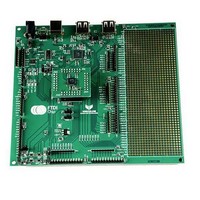
V2-EVAL (UK) FTDI, V2-EVAL (UK) Datasheet - Page 30

V2-EVAL (UK)
Manufacturer Part Number
V2-EVAL (UK)
Description
Interface Modules & Development Tools USB Vinculum-II Eval Kit UK Power Supply
Manufacturer
FTDI
Datasheet
1.V2-EVAL-EXT48.pdf
(54 pages)
Specifications of V2-EVAL (UK)
Interface Type
USB, Serial, UART, FIFO, SPI
Data Bus Width
Serial, 8 bit
Operating Supply Voltage
4.75 V to 5.25 V
Product
Interface Modules
For Use With/related Products
VNC2
Lead Free Status / RoHS Status
Lead free / RoHS Compliant
5.10
Four LEDs is provided on board. The LEDs enabled or disabled via jumpers JP7 – JP10. The LEDs are
controlled by the IOBUS signals on the VNC2.
Note - LED5 is also connected to jumper JP1 on the board. Care should be taken to ensure that LED is
not being driven by JP1 when controlling the LED from the VNC2.
Designator
LED3
LED4
LED5
LED6
Notes:
5.11
Every user-defined LED have an enable/disable jumper. When jumper is closed LED will be illuminate
when driven low by one of the VNC2 pins. When jumper is opened LED is disconnected from the VCN2
pin.
Designator
JP7
JP8
JP9
JP10
Table 5.14
Table 5.15
(39)
(39)
Figure 5.15
Figure 5.16
LED5 is also connected to jumper JP1 on the board. Care should be taken to ensure
that LED is not being driven by JP1 when controlling the LED from the VNC2.
User LEDs. LED3 – LED6.
LED enable/disable jumpers JP10 – JP14.
User LEDs connections.
LED Enable/Disable Jumpers.
User LEDs.
LED Enable/Disable jumpers.
Copyright © 2010 Future Technology Devices International Limited
32-PIN
12
14
-
-
V2-EVAL Vinculum II Evaluation Board Datasheet Version 1.0
LED affected
LED3
LED4
LED5
LED6
VCN2 pin number
48-PIN
12
13
46
45
Document Reference No.: FT_000247
Clearance No.: FTDI#148
64-PIN
12
13
29
31
29


