UM232R FTDI, UM232R Datasheet
UM232R
Specifications of UM232R


Related parts for UM232R


UM232R Summary of contents
Page 1
... Future Technology Devices International Ltd UM232R USB - Serial UART Development Module Future Technology Devices International Ltd (FTDI) Unit 1, 2 Seaward Place, Centurion Business Park, Glasgow, G41 1HH, United Kingdom E-Mail (Support): Neither the whole nor any part of the information contained in, or the product described in this manual, may be adapted or reproduced in any material or electronic form without the prior written consent of the copyright holder ...
Page 2
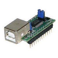
... Introduction The UM232R is a development module which uses FTDI‟s FT232RL, the one of FTDI‟s range of USB to UART interface integrated circuit devices. The FT232RL is a USB to serial UART interface with optional clock generator output, and the FTDIChip-ID™ security dongle feature. In addition, asynchronous and synchronous bit bang interface modes are available. The FT232RL adds two new functions compared with its predecessors, effectively making it a “ ...
Page 3
... Internal EEPROM Configuration ................................................ 23 10 Contact Information ...................................................................... 25 Appendix A – List of Tables and Figures ........................................................ 26 Appendix B – Revision History ........................................................................... 27 © Copyright 2009 Future Technology Devices International Ltd UM232R USB - Serial UART Development Module Incorporating Clock Generator Document Reference No.: FT_000051 Datasheet Version 1.04 Clearance No.: FTDI# 125 2 ...
Page 4
... Party Drivers are also available for various other operating systems - visit for details. © Copyright 2009 Future Technology Devices International Ltd UM232R USB - Serial UART Development Module Incorporating Clock Generator Royalty-Free D2XX Direct Drivers (USB Drivers + DLL S/W Interface): Windows 7 32,64-bit ...
Page 5
... USB configurations. © Copyright 2009 Future Technology Devices International Ltd UM232R USB - Serial UART Development Module Incorporating Clock Generator On board jumper allows for selection of USB bus powered supply or self powered supply. Integrated 3.3V level converter for USB I/O. ...
Page 6
... Key Features This section summarises the key features and enhancements of the FT232RL IC device which is used on the UM232R Module. For further details, consult the FT232R datasheet, which is available from www.ftdichip.com. Integrated Clock Circuit - Previous generations of FTDI‟s USB UART devices required an external crystal or ceramic resonator ...
Page 7
... QFN-32 package ( FT232RQ). Both packages are lead ( Pb ) free, and use a „green‟ compound. Both packages are fully compliant with European Union directive 2002/95/EC. © Copyright 2009 Future Technology Devices International Ltd UM232R USB - Serial UART Development Module Incorporating Clock Generator 14 ) and „x’ can be a sub-integer of the value 0, Document Reference No ...
Page 8
... UM232R Pin Out and Signal Descriptions 4.1 UM232R Pin Out Figure 4.1 Module Pin Out and Jumper Locations © Copyright 2009 Future Technology Devices International Ltd UM232R USB - Serial UART Development Module Incorporating Clock Generator Document Reference No.: FT_000051 Datasheet Version 1.04 Clearance No.: FTDI# 125 ...
Page 9
... PWR or 14. 15, 21 VCC Output To use the UM232R module in a self powered configuration ensure that jumper J2 pins 1 and 2 are not connected together, and apply an external 3.5V to 5.25V supply to one of these pins. Pull up resistor pin connection 2. Connect to pin 20 (RST self powered 17 PU1 Control configuration ...
Page 10
... This pin is internally connected to the VCC DIP pins. Remove the jumper connector in a self powered design. Table 4.3 Jumper J2 Pin Description © Copyright 2009 Future Technology Devices International Ltd UM232R USB - Serial UART Development Module Incorporating Clock Generator Document Reference No.: FT_000051 Datasheet Version 1.04 Clearance No.: FTDI# 125 ...
Page 11
... CBUS0, CBUS1, CBUS2, CBUS3 BitBangRDn CBUS0, CBUS1, CBUS2, CBUS3 Table 4.4 CBUS Signal Options © Copyright 2009 Future Technology Devices International Ltd UM232R USB - Serial UART Development Module Incorporating Clock Generator Section 9. Description Enable transmit data for RS485 Goes low after the device is configured by USB, then high during USB suspend ...
Page 12
... The FT232RL is supplied in a RoHS compliant 28 pin SSOP package. The package is lead (Pb) free and uses a „green# compound. The date code format is YYXX where digit week number digit year number. The UM232R module uses exclusively lead free components, and are fully compliant with European Union directive 2002/95/EC. © Copyright 2009 Future Technology Devices International Ltd UM232R USB - Serial UART Development Module Incorporating Clock Generator Document Reference No ...
Page 13
... Operating Supply Current Icc2 Operating Supply Current Table 6.2 Operating Voltage and Current © Copyright 2009 Future Technology Devices International Ltd UM232R USB - Serial UART Development Module Incorporating Clock Generator Value -65°C to 150°C 168 Hours (IPC/JEDEC J-STD-033A MSL Level 3 Compliant)* -40° ...
Page 14
... Input Switching Threshold VHys Input Switching Hysteresis Table 6.7 UART and CBUS I/O Pin Characteristics (VCCIO = 3.3V, High Drive Level) © Copyright 2009 Future Technology Devices International Ltd UM232R USB - Serial UART Development Module Incorporating Clock Generator Minimu Maximu Typical m 3.2 4 ...
Page 15
... Table 6.10 USB I/O Pin (USBDP, USBDM) Characteristics *** Driver Output Impedance includes the internal USB series resistors on USBDP and USBDM pins © Copyright 2009 Future Technology Devices International Ltd UM232R USB - Serial UART Development Module Incorporating Clock Generator Minimu Maximu Typical m 2 ...
Page 16
... The internal Clock Oscillator has the following characteristics: Parameter Frequency of Operation Clock Period Duty Cycle Table 6.12 Internal Clock Characteristics © Copyright 2009 Future Technology Devices International Ltd UM232R USB - Serial UART Development Module Incorporating Clock Generator Unit Years Cycles Value Minimum Typical 11 ...
Page 17
... Figure 7.1 Bus Powered Configuration Figure 7.1 illustrates the UM232R module in a typical USB bus powered design configuration. This can easily be done by fitting the jumper link on J2, as shown above. The UM232R is supplied in this configuration by default. A USB Bus Powered device gets its power from the USB bus. Basic rules for USB Bus Power devices are as follows plug-in to USB, the device must draw no more than 100mA ...
Page 18
... MCU Figure 7.2 Self-Powered Configuration Figure 7.2 illustrates the UM232R in a typical USB self powered configuration. In this case the link on jumper J2 is removed, and an external supply is connected to the module VCC pins. Figure 7.2 illustrates a self powered design which has a 3.5V – 5V supply. ...
Page 19
... MCU. If the MCU is handling power management functions, then a CBUS pin can be configured as PWREN# and should also be connected to an I/O pin of the MCU. © Copyright 2009 Future Technology Devices International Ltd UM232R USB - Serial UART Development Module Incorporating Clock Generator Document Reference No.: FT_000051 Datasheet Version 1.04 Clearance No ...
Page 20
... EEPROM. A high-power bus powered device must use this descriptor in the internal EEPROM to inform the system of its power requirements. © Copyright 2009 Future Technology Devices International Ltd UM232R USB - Serial UART Development Module Incorporating Clock Generator UM232R © FTDI 2008 ...
Page 21
... VCCIO from the 3V3OUT pin of the FT232R. © Copyright 2009 Future Technology Devices International Ltd UM232R USB - Serial UART Development Module Incorporating Clock Generator Document Reference No.: FT_000051 Datasheet Version 1.04 Clearance No ...
Page 22
... J1), or with 3.3V from the FT232R‟s 3V3OUT pin (connect together pins 1 and shown) the supply to UM232R‟s 3V3 pin can also be used to supply up to 50mA to external logic. Please note the following in relation to bus powered designs of this type: i) PWREN# or SLEEP‟ ...
Page 23
... UM232R Module Circuit Schematic Figure 8.1 Module Circuit Schematic © Copyright 2009 Future Technology Devices International Ltd UM232R USB - Serial UART Development Module Incorporating Clock Generator Document Reference No.: FT_000051 Datasheet Version 1.04 Clearance No.: FTDI# 125 22 ...
Page 24
... Following a power-on reset or a USB reset the FT232R will scan its internal EEPROM and read the USB configuration descriptors stored there. The default values programmed into the internal EEPROM in the FT232RL used on the UM232R are shown in Table 8.1. Parameter USB Vendor ID (VID) ...
Page 25
... Product ID in their design can apply to FTDI for a free block of unique PIDs. Contact FTDI Support (sales1@ftdichip.com) for this service. © Copyright 2009 Future Technology Devices International Ltd UM232R USB - Serial UART Development Module Incorporating Clock Generator Document Reference No.: FT_000051 Datasheet Version 1.04 Clearance No.: FTDI# 125 24 ...
Page 26
... Please visit the Sales Network page of the FTDI Web site for the contact details of our distributor(s) and sales representative(s) in your country. © Copyright 2009 Future Technology Devices International Ltd UM232R USB - Serial UART Development Module Incorporating Clock Generator cn.sales@ftdichip.com cn.support@ftdichip.com cn.admin@ftdichip.com http://www ...
Page 27
... Table 6.11 EEPROM Characteristics .................................................................................................. 15 Table 6.12 Internal Clock Characteristics ...................................................................................... 15 Table 9.1 Default Internal EEPROM Configuration ..................................................................... 23 List of Figures Figure 1.1 – UM232R USB Serial UART Development Module .................................................. 1 Figure 4.1 Module Pin Out and Jumper Locations ........................................................................ 7 Figure 5.1 UM232R Module Dimensions ......................................................................................... 11 Figure 7.1 Bus Powered Configuration ............................................................................................ 16 Figure 7 ...
Page 28
... Table 4.1 (PU1 and PU2) Update Contact information Update Added Windows 7 32,64 bit driver support Changed references of MPROG to FT_PROG © Copyright 2009 Future Technology Devices International Ltd UM232R USB - Serial UART Development Module Incorporating Clock Generator August 2005 December 2005 January 2006 January 2006 ...