DB-PLCC44-LPC952 FDI, DB-PLCC44-LPC952 Datasheet - Page 2
DB-PLCC44-LPC952
Manufacturer Part Number
DB-PLCC44-LPC952
Description
Interface Modules & Development Tools DB-PLCC44-LPC952 w/ P89LPC952FA LD REV1
Manufacturer
FDI
Datasheet
1.DB-PLCC44-LPC952.pdf
(2 pages)
Specifications of DB-PLCC44-LPC952
Interface Type
I2C, SPI, UART
Operating Supply Voltage
5 V
Product
Interface Modules
For Use With/related Products
P89LPC952
Lead Free Status / RoHS Status
Lead free / RoHS Compliant


Headers – The
footprint for easy probing of signals or to support prototyping or wire-wrapping. Consult the
schematic if there are any questions about pin alignment from the microcontroller to the headers.
Power – The USB-Dongle provides the regulated 3.3V power required by the DB-PLCC44-LPC952. The DB has a
power measurement jumper, JP1, to allow the user to easily measure the power consumption of the microcontroller.
In the artwork, JP1 pin 1 is shorted to pin 2 so the board is continuously powered. The board can be easily modified
by cutting JP1 and loading a standard 0.10” header.
LED - A green activity or status LED is provided at location D1 on the Derivative Board. This LED can be used to
indicate when the microcontroller is being programmed or for other types of user activity under software control.
Crystal or Clock Frequency - The
frequency of 7.373 MHz so no external crystal is needed on the DB.
Rev 2 8/14/2008
Technical Details
The
edge finger connector to interface to
Ordering Information
Board Dimensions 2.103” x 1.4”
DB-PLCC44-LPC952
the USB-Dongle.
DB-PLCC44-LPC952
Availability: Stock
www.mouser.com
All brand names and product names are trademarks or registered trademarks of their respective holders.
Order Online at:
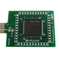
Example of USB-Dongle and Derivative Board
uses a PCB
USB-Dongle
DB-PLCC44-LPC952
brings every pin of the microcontroller out to a standard 0.10” spacing header
The USB-Dongle includes a 14 pin connector to the Derivative Board
Switched Power (3V for ICP) or
Reset (High True for 8051 ISP)
that utilizes the following signals. Not all signals are used on all
PCL/SCL (ICP/I2C)
TXD (UART)
SCLK (SPI)
MSIO (SPI)
ISP/ICPn
Ground
is clocked by the on-board oscillator in the LPC952 at a
DB-HVSON10-LPC9103
Target Interface
Derivative Boards:
E-mail:
(800) 278-0293 Phone
(256) 883-1241 FAX
FDI Contact Info:
www.teamfdi.com
sales@teamfdi.com
5V (USB power, unswitched)
(for ICP & LPC2000 ARM)
PSEN/P0.14 (ISP entry)
PDA/SDA (ICP/I2C)
Reset (Low True)
3V (unswitched)
RXD (UART)
DB-PLCC44-LPC952
MOSI (SPI)
Related parts for DB-PLCC44-LPC952
Image
Part Number
Description
Manufacturer
Datasheet
Request
R

Part Number:
Description:
Interface Modules & Development Tools DB-PLCC44-SKT Rev 2 44pZIF PLCC skt load
Manufacturer:
FDI
Datasheet:

Part Number:
Description:
14 Pin Dip Quadrature Oscillator
Manufacturer:
Frequency Devices, Inc.
Datasheet:
Part Number:
Description:
Inline Fuseholder, 5x20 / 6.3x32 mm
Manufacturer:
SCHURTER [Schurter Inc.]
Datasheet:

Part Number:
Description:
Display Modules & Development Tools uEZ GUI LPC2478 Dev 4.3 WQVGA Touch LCD
Manufacturer:
FDI
Datasheet:

Part Number:
Description:
Display Modules & Development Tools NXP PCF2123 RTC Demo Kit, Rev 2
Manufacturer:
FDI
Datasheet:

Part Number:
Description:
Display Modules & Development Tools Sngl Chip LCD Board w/ 8-Char Alpha LCD
Manufacturer:
FDI

Part Number:
Description:
Display Modules & Development Tools Single Chip Solution LCD User Interface
Manufacturer:
FDI

Part Number:
Description:
Display Modules & Development Tools Kit for LCD Demo
Manufacturer:
FDI
Datasheet:

Part Number:
Description:
Interface Modules & Development Tools DBHVSON10LPC9103 w/ LPC9103 loaded Rev 1
Manufacturer:
FDI
Datasheet:

Part Number:
Description:
Interface Modules & Development Tools DB-DIP8-LPC901 w/ LPC901 loaded Rev 1
Manufacturer:
FDI
Datasheet:

