RDK-242 Power Integrations, RDK-242 Datasheet
RDK-242
Specifications of RDK-242


Related parts for RDK-242


RDK-242 Summary of contents
Page 1
... The products and applications illustrated herein (including transformer construction and circuits external to the products) may be covered by one or more U.S. and foreign patents, or potentially by pending U.S. and foreign patent applications assigned to Power Integrations. A complete list of Power Integrations' patents may be found at www.powerint.com. Power Integrations grants its customers a license under certain patent rights as set forth at < ...
Page 2
... Available Standby Output Power.......................................................................30 9.5 Regulation .........................................................................................................31 9.5.1 Load ...........................................................................................................31 9.5.2 Line ............................................................................................................32 9.6 Efficiency ...........................................................................................................33 9.6.1 Load ...........................................................................................................33 10 Power Limit ...........................................................................................................35 11 Thermal Performance ...........................................................................................36 12 Waveforms............................................................................................................37 12.1 Drain Voltage and Current, Normal Operation...................................................37 Power Integrations, Inc. Tel: +1 408 414 9200 Fax: +1 408 414 9201 www.powerint.com Page ...
Page 3
... Although this board is designed to satisfy safety isolation requirements, the engineering prototype has not been agency approved. Therefore, all testing should be performed using an isolation transformer to provide the AC input to the prototype board. Page sec .................................................................54 Power Integrations Tel: +1 408 414 9200 Fax: +1 408 414 9201 www.powerint.com ...
Page 4
... Introduction This engineering report describes a power supply employing the Power Integrations ® TOPSwitch -JX TOP266VG. This power supply operates over a universal input range and provides output. It has been designed and tested to operate open frame with an ambient temperature environment °C. The TOPSwitch-JX, by design, maintains virtually constant efficiency across a very wide load range without using special operating modes to meet specific load thresholds ...
Page 5
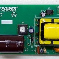
... Figure 1 – Populated Circuit Board Photograph, Component Side. Figure 2 – Populated Circuit Board Photograph, Solder Side. Page Power Integrations Tel: +1 408 414 9200 Fax: +1 408 414 9201 www.powerint.com ...
Page 6
... Required average efficiency at 25, 50, 75 and 100 % of P OUT Environmental Conducted EMI Safety Line Surge Differential Mode (L1-L2) Common Mode (L1/L2-PE) Ambient Temperature Power Integrations, Inc. Tel: +1 408 414 9200 Fax: +1 408 414 9201 www.powerint.com Symbol Min Typ Max 85 264 V IN ...
Page 7
... Schematic Page Figure 3 – Schematic. Tel: +1 408 414 9200 Fax: +1 408 414 9201 Power Integrations www.powerint.com ...
Page 8
... Line sensing is provided by resistors R1 and R2 and sets the line undervoltage and overvoltage thresholds. The combined value of these resistors was increased from the standard 4 M to 10.2 M. This reduced the resistor, and therefore contribution to no- Power Integrations, Inc. Tel: +1 408 414 9200 Fax: +1 408 414 9201 www.powerint.com ...
Page 9
... In many designs a resistor value of less than 50 may be used in series with C4 to damp out high frequency ringing and improve EMI but this was not necessary in this case. Page rating of the internal DSS Power Integrations Tel: +1 408 414 9200 Fax: +1 408 414 9201 www.powerint.com ...
Page 10
... PCB area for heatsinking so that their temperatures track. In practice the diodes current share quite effectively as can be demonstrated by monitoring their individual temperatures. Power Integrations, Inc. Tel: +1 408 414 9200 Fax: +1 408 414 9201 www.powerint.com ). This reduced the output diode voltage stress ...
Page 11
... The line sensing resistors R1 and R2, in conjunction with R12, set the undervoltage and overvoltage thresholds for U1. R12 provides Page Power Integrations Tel: +1 408 414 9200 Fax: +1 408 414 9201 www.powerint.com ...
Page 12
... U2A and D10 current flows though the optocoupler LED and provides feedback to the primary. This arrangement acts to limit the rate of rise of the output voltage until it reaches regulation and eliminates the capacitor that is typically placed across U3 to provide the same function. Power Integrations, Inc. Tel: +1 408 414 9200 Fax: +1 408 414 9201 www.powerint.com Page ...
Page 13
... PCB Layout Page Figure 4 – Printed Circuit Board Layout. Tel: +1 408 414 9200 Fax: +1 408 414 9201 Power Integrations www.powerint.com ...
Page 14
... M, 5%, 1/4 W, Thick Film, 1206 M, 5%, 1/4 W, Thick Film, 1206 k, 5%, 1/2 W, Carbon Film 10 , 5%, 1/4 W, Thick Film, 1206 Power Integrations, Inc. Tel: +1 408 414 9200 Fax: +1 408 414 9201 www.powerint.com Part Number Mfg LE104 OKAYA ELECT Nippon Chemi- EKXG401ELL820MM25S Con 562R5GAD47 Vishay Nippon Chemi- ...
Page 15
... Page ERJ-3EKF1913V ERJ-6ENF1432V ERJ-6GEYJ6R8V ERJ-8GEYJ220V ERJ-6GEYJ111V ERJ-6GEYJ470V ERJ-6ENF8662V ERJ-6ENF1002V YC2504 SNX-R1521 TOP266VG LTV-817D LMV431ACZ P6KE180ARLG ZMM5245B-7 Power Integrations Tel: +1 408 414 9200 Fax: +1 408 414 9201 www.powerint.com Panasonic Panasonic Panasonic Panasonic Panasonic Panasonic Panasonic Panasonic Ying Chin Santronics Power Integrations Liteon ...
Page 16
... Copper Foil Tape: 2.0 mils thick, 9.0 mm wide. See Figure 7 below to prepare. [12] Varnish. [13] Power Integrations, Inc. Tel: +1 408 414 9200 Fax: +1 408 414 9201 www.powerint.com Figure 5 – Transformer Electrical Diagram. 1 second, 60 Hz, from pins 1-6 to pins 7-12 Pins 4-6, all other windings open, measured at 100 kHz, 0 ...
Page 17
... Transformer Build Diagram Bias, AWG#24x2 6T Shielding, Copper 1T Primary,58T #AWG30 Cancel,13T, #AWG29 x 2 Page 3.0mm margin tape Teflon tubes Figure 6 – Transformer Build Diagram. Figure 7 – Shield. Tel: +1 408 414 9200 Fax: +1 408 414 9201 Secondary, 11,12 AWG#23x2 6T 7,8 NC Power Integrations www.powerint.com ...
Page 18
... Apply 2 layers of tape item [9]. Outer insulation Grind core. Cover outside the core with tape item [11]. Assemble core and varnish [13] Final Assembly Power Integrations, Inc. Tel: +1 408 414 9200 Fax: +1 408 414 9201 www.powerint.com Figure 8 – Completed Transformer. Page ...
Page 19
... Transformer Design Spreadsheet ACDC_TOPSwitchJX_020 110; Rev.1.2; Copyright Power Integrations 2010 INPUT ENTER APPLICATION VARIABLES VACMIN 85 VACMAX 265 12.00 PO_AVG 30.00 PO_PEAK Heatsink Type PCB Enclosure Open Frame n 0. 3.00 CIN 82.0 ENTER TOPSWITCH-JX VARIABLES TOPSwitch-JX TOP266V Chosen Device KI 0.4725 ILIMITMIN_EXT ...
Page 20
... Bobbin 0. INPUT VOLTAGE PARAMETERS VMIN VMAX CURRENT WAVEFORM SHAPE PARAMETERS DMAX IAVG IP IR IRMS Power Integrations, Inc. Tel: +1 408 414 9200 Fax: +1 408 414 9201 www.powerint.com 95 Volts 445 Volts 4.0 M-ohms 27 Volts 5.1 k-ohms 1.2 1.11 1.01 A 0.97 A 12.88 ...
Page 21
... Output Capacitor RMS Ripple Current Secondary Bare Conductor minimum circular mils Secondary Wire Gauge (Rounded up to next larger standard AWG value) Secondary Minimum Bare Conductor Diameter Secondary Maximum Outside Diameter for Triple Insulated Wire Maximum Secondary Insulation Wall Thickness Power Integrations www.powerint.com ...
Page 22
... DIAS2 ODS2 3rd output VO3 IO3_AVG PO3_AVG VD3 NS3 ISRMS3 IRIPPLE3 PIVS3 Power Integrations, Inc. Tel: +1 408 414 9200 Fax: +1 408 414 9201 www.powerint.com 611 Volts Maximum Drain Voltage Estimate (Includes Effect of Leakage Inductance) 51 Volts Output Rectifier Maximum Peak Inverse Voltage ...
Page 23
... N/A mm Minimum Bare Conductor Diameter N/A mm Maximum Outside Diameter for Triple Insulated Wire 30 Watts Total Continuous Output Power N/A If negative output exists enter Output number; eg: If VO2 is negative output, enter 2 Power Integrations Tel: +1 408 414 9200 Fax: +1 408 414 9201 www.powerint.com ...
Page 24
... All measurements were performed at room temperature input frequency. All output measurements were taken at the output terminals. 9.1 Active Mode Efficiency Figure 9 – Efficiency vs. Input Voltage, Room Temperature, 60 Hz. Power Integrations, Inc. Tel: +1 408 414 9200 Fax: +1 408 414 9201 www.powerint.com Load (%) 115 V 230 100 Page ...
Page 25
... Tel: +1 408 414 9200 Fax: +1 408 414 9201 (W) Efficiency (%) 71.00 76.60 78.85 80.43 81.79 84.39 85.30 85.47 85.49 85.39 85.60 85.11 84.65 84.58 84.39 84.14 (W) Efficiency (%) 65.52 71.77 73.95 75.10 76.95 82.12 83.86 84.51 84.76 85.09 85.04 85.65 84.86 84.18 85.21 86.13 Power Integrations www.powerint.com ...
Page 26
... Percent of Full Load 100 Average US EISA (2007) requirement ENERGY STAR 2.0 requirement Power Integrations, Inc. Tel: +1 408 414 9200 Fax: +1 408 414 9201 www.powerint.com Efficiency (%) 115 VAC 230 VAC 85.47 84.51 85.60 85.04 84.65 84.86 84.14 86.13 84.97 85. Page ...
Page 27
... This requirement supersedes the legislation from individual US States (for example CEC in California). Page Minimum Efficiency in Active Mode of Operation O 0.5 P 0.09 0. natural logarithm ) Maximum Power for No-load AC-DC EPS O 0.5 W Tel: +1 408 414 9200 Fax: +1 408 414 9201 st , 2008 must meet minimum 0.5 O Power Integrations www.powerint.com ...
Page 28
... Active Mode Efficiency Low Voltage Models (V Nameplate Output (P > > No-load Energy Consumption (both models) Nameplate Output ( < 250 W Power Integrations, Inc. Tel: +1 408 414 9200 Fax: +1 408 414 9201 www.powerint.com st , 2008. ) Minimum Efficiency in Active Mode of Operation O 0.48 P 0.0626 ...
Page 29
... Input Voltage (VAC) V Input Line P (mW) OUT 63.36 12 100 64.10 12 115 65.00 12 132 66.27 12 180 71.33 12 230 77.23 12 240 79.36 12 264 88.03 Tel: +1 408 414 9200 Fax: +1 408 414 9201 88.0 79.4 77.2 200 220 240 260 Power Integrations www.powerint.com ...
Page 30
... The chart below shows the available output power vs. line voltage for an input power and 2.5 2 1 100 120 Power Integrations, Inc. Tel: +1 408 414 9200 Fax: +1 408 414 9201 www.powerint.com 140 160 180 Input (VAC) Figure 11 – Available Standby Power Input 2 W Input 3 W Input 200 ...
Page 31
... Regulation 9.5.1 Load 12.5 12.4 12.3 12.2 12.1 12 11.9 11.8 11.7 11.6 11 Figure 12 – Load Regulation, Room Temperature. Page Load (%) Tel: +1 408 414 9200 Fax: +1 408 414 9201 115 V 230 V 80 100 Power Integrations www.powerint.com ...
Page 32
... Figure 13 – Line Regulation, Room Temperature, Full Load. Power Integrations, Inc. Tel: +1 408 414 9200 Fax: +1 408 414 9201 www.powerint.com 140 160 180 200 Input Voltage (VAC) 220 240 260 Page ...
Page 33
... Efficiency 9.6.1 Load Figure 14 – Load Efficiency, Room Temperature. Page Load (%) Tel: +1 408 414 9200 Fax: +1 408 414 9201 115 V 230 100 Power Integrations www.powerint.com ...
Page 34
... Figure 15 – Line Efficiency at Full-load, Room Temperature. Power Integrations, Inc. Tel: +1 408 414 9200 Fax: +1 408 414 9201 www.powerint.com 85.01 84.48 140 160 180 200 Input Voltage (VAC) 86.21 86.09 85.40 ...
Page 35
... Figure 16 – Maximum Output Power vs. Line Voltage. Page 55.11 53.91 51.39 140 160 180 Input Voltage (VAC) Tel: +1 408 414 9200 Fax: +1 408 414 9201 55.59 55.59 55.71 200 220 240 260 Power Integrations www.powerint.com ...
Page 36
... Transformer wire 6 T1 Transformer core 7 C14 Output Capacitor 8 C15 Output Capacitor VR1 Power Integrations, Inc. Tel: +1 408 414 9200 Fax: +1 408 414 9201 www.powerint.com 85 VAC, 47 Hz; Description T A Bridge Diode TOPSwitch Output Diode Output Diode Zener Clamp 264 VAC ˚ ˚C ...
Page 37
... Figure 18 – 115 VAC 60 Hz, Full Load. Upper 100 V / div. DRAIN , 0 s / div. Lower: I DRAIN Figure 20 – 264 VAC 50 Hz, Full Load. Upper 100 V / div. DRAIN , 0 s / div. Lower: I DRAIN Power Integrations Tel: +1 408 414 9200 Fax: +1 408 414 9201 www.powerint.com ...
Page 38
... div OUT – 264 VAC 50 Hz, Full Load. Figure 23 Upper 0 div. DRAIN Lower div OUT Power Integrations, Inc. Tel: +1 408 414 9200 Fax: +1 408 414 9201 www.powerint.com – 85 VAC 47 Hz, No-load. Figure 22 Upper Lower: V – 264 VAC 50 Hz, Full Load. Figure 24 Upper: I ...
Page 39
... DRAIN Lower div OUT Page – 85 VAC 47 Hz, No-load. Figure 26 Upper Lower: V – 264 VAC 50 Hz, No-load. Figure 28 Upper Lower: V Tel: +1 408 414 9200 Fax: +1 408 414 9201 , 100V / div. DRAIN . , div OUT , 100V / div. DRAIN . , div OUT Power Integrations www.powerint.com ...
Page 40
... The output diodes had the highest recorded temperature during an output short circuit at 85 VAC (input power of 2.2 W). A temperature of 45 C was well within the temperature limits of the diodes. Figure 31 – 85 VAC 60 Hz Short Circuit T D8 45.2˚ Power Integrations, Inc. Tel: +1 408 414 9200 Fax: +1 408 414 9201 www.powerint.com , and V DRAIN ...
Page 41
... PIVS: 56.41 V. Page Figure 34– ~ 55. 264 VAC. CH1 100 V / div. DRAIN CH3 0. div. DRAIN CH2 div. OUT CH4 div. OUT Figure 36 – 264 VAC Max Power 637.5 V. DRAIN PIVS: 57.08 V. Power Integrations Tel: +1 408 414 9200 Fax: +1 408 414 9201 www.powerint.com ...
Page 42
... Figure 37 – OVP at 85 VAC, No-load. OVP Trip Point = 18.75 V. Figure 39 – OVP at 264 VAC, No-load. OVP Trip Point = 18.96 V. Power Integrations, Inc. Tel: +1 408 414 9200 Fax: +1 408 414 9201 www.powerint.com Figure 38 – OVP at 85 VAC, Full Load. OVP Trip Point = 16.67 V. ...
Page 43
... Top: Load Current, 0 div. Bottom 100 mV / div. OUT Time Scale div. Figure 44 – Transient Response, 230 VAC, 75%↔100% Step Load. Top: Load Current, 0 div. Bottom 100 mV / div. OUT Time Scale div. Power Integrations Tel: +1 408 414 9200 Fax: +1 408 414 9201 www.powerint.com ...
Page 44
... Figure 45 – Oscilloscope Probe Prepared for Ripple Measurement. (End Cap and Ground Lead Removed) Figure 46 – Oscilloscope Probe with Probe Master (www.probemaster.com) 4987A BNC Adapter. (Modified with wires for ripple measurement, and two parallel decoupling capacitors added) Power Integrations, Inc. Tel: +1 408 414 9200 Fax: +1 408 414 9201 www.powerint.com ...
Page 45
... Figure 49 – Ripple, 264 VAC 50 Hz, Full Load. 500 ms /div. Page Figure 48 – Ripple, 85 VAC 47 Hz, Full Load. 10 ms, 100 mV / div. Figure 50 – Ripple, 264 VAC 50 Hz, Full Load /div. Power Integrations Tel: +1 408 414 9200 Fax: +1 408 414 9201 www.powerint.com ...
Page 46
... Figure 51 – Ripple, 85 VAC, No-load div. Figure 53– Ripple, 230 VAC, No-load div. Power Integrations, Inc. Tel: +1 408 414 9200 Fax: +1 408 414 9201 www.powerint.com Figure 52 – Ripple, 115 VAC, No-load div. Figure 54 – Ripple, 264 VAC, No-load. ...
Page 47
... Control Loop Measurements 13.1 115 VAC Maximum Load Figure 55 – Gain-Phase Plot, 115 VAC, Maximum Steady State Load. Crossover Frequency = 3.5 kHz Phase Margin = 51.5. Page Power Integrations Tel: +1 408 414 9200 Fax: +1 408 414 9201 www.powerint.com ...
Page 48
... VAC Maximum Load Figure 56 – Gain-Phase Plot, 230 VAC, Maximum Steady State Load. Crossover Frequency = 637.8 Hz, Phase Margin = 71.7. Power Integrations, Inc. Tel: +1 408 414 9200 Fax: +1 408 414 9201 www.powerint.com Page ...
Page 49
... Quasi peak and average measurement have both ≥ margin to Class B limits. 14.1 Output Grounded Figure 57 – Phase L1: Conducted EMI, Maximum Steady State Load, 115 VAC, 60 Hz, and EN55022 B Page Limits. Output Terminal Grounded. Tel: +1 408 414 9200 Fax: +1 408 414 9201 Power Integrations www.powerint.com ...
Page 50
... Figure 58 – Phase N: Conducted EMI, Maximum Steady State Load, 115 VAC, 60 Hz, and EN55022 B Figure 59 – Phase L1: Conducted EMI, Maximum Steady State Load, 230 VAC, 60 Hz, and EN55022 B Power Integrations, Inc. Tel: +1 408 414 9200 Fax: +1 408 414 9201 www.powerint.com Limits. Output Terminal Grounded. ...
Page 51
... Figure 60 – Phase N: Conducted EMI, Maximum Steady State Load, 230 VAC, 60 Hz, and EN55022 B Page Limits. Output Terminal Grounded. Tel: +1 408 414 9200 Fax: +1 408 414 9201 Power Integrations www.powerint.com ...
Page 52
... Output Floating Figure 61 – Phase L1: Conducted EMI, Maximum Steady State Load, 115 VAC, 60 Hz, and EN55022 B Figure 62 – Phase N: Conducted EMI, Maximum Steady State Load, 115 VAC, 60 Hz, and EN55022 B Power Integrations, Inc. Tel: +1 408 414 9200 Fax: +1 408 414 9201 www.powerint.com Limits ...
Page 53
... Figure 63 – Phase L1: Conducted EMI, Maximum Steady State Load, 230 VAC, 60 Hz, and EN55022 B Figure 64 – Phase N: Conducted EMI, Maximum Steady State Load, 230 VAC, 60 Hz, and EN55022 B Page Limits. Output Terminal Floating. Limits. Output Terminal Floating. Tel: +1 408 414 9200 Fax: +1 408 414 9201 Power Integrations www.powerint.com ...
Page 54
... Differential Mode Surge, 1 Surge Phase Voltage Angle (kV) ( 270 1.2 90 1.2 270 Power Integrations, Inc. Tel: +1 408 414 9200 Fax: +1 408 414 9201 www.powerint.com sec Generator Number of Impedance Strikes ( sec Generator ...
Page 55
... Figure 65 – Fast AC Reset Circuit Implementation for TOPSwitch-JX. Page Should a latching OVP condition occur, the circuit below = -27 A (typ) and reset the latch when to exceed I X X(TH) is desirable to allow using a higher resistance R1 and lower R Tel: +1 408 414 9200 Fax: +1 408 414 9201 Power Integrations www.powerint.com ...
Page 56
... R19). Figure 66 – Optocoupler Darlington Configuration to Reduce Feedback Current and No-load Input Power. Power Integrations, Inc. Tel: +1 408 414 9200 Fax: +1 408 414 9201 www.powerint.com = 3 ...
Page 57
... Input Voltage(VAC) V Input Line P (mW) OUT 46.30 12 100 47.52 12 115 48.46 12 132 50.00 12 180 55.21 12 230 62.92 12 240 64.28 12 264 67.17 Tel: +1 408 414 9200 Fax: +1 408 414 9201 62.92 55.21 185 205 225 Power Integrations www.powerint.com ...
Page 58
... Revision History Date Author 01-Mar-10 CA Power Integrations, Inc. Tel: +1 408 414 9200 Fax: +1 408 414 9201 www.powerint.com Revision Description & changes 1.2 Initial Release Reviewed Apps & Mktg Page ...
Page 59
... Power Integrations reserves the right to make changes to its products at any time to improve reliability or manufacturability. Power Integrations does not assume any liability arising from the use of any device or circuit described herein. POWER INTEGRATIONS MAKES NO WARRANTY HEREIN AND SPECIFICALLY DISCLAIMS ALL WARRANTIES INCLUDING, WITHOUT LIMITATION, THE IMPLIED WARRANTIES OF MERCHANTABILITY, FITNESS FOR A PARTICULAR PURPOSE, AND NON-INFRINGEMENT OF THIRD PARTY RIGHTS ...