PIC-GSM Olimex Ltd., PIC-GSM Datasheet
PIC-GSM
Specifications of PIC-GSM


Related parts for PIC-GSM


PIC-GSM Summary of contents
Page 1
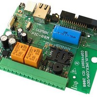
... PIC-GSM development board All boards produced by Olimex are ROHS compliant Copyright(c) 2008, OLIMEX Ltd, All rights reserved Rev.A, June 2008 Users Manual ...
Page 2
... Normal phone hook can be connected to this board and to allow user to speak, listen, taking and placing phone calls as normal stand alone cellular phone. PIC-GSM can be connected to PC with the USB connector it have and it is recognized as modem which could be used to add internet via GPRS to your computer (imagine how useful is this for your mountain house if there is no internet but only cellular network!) ...
Page 3
... Software: Important: If your board does not work, first try to charge the battery as 1.8 meter USB A-B cable to connect to USB host on PC. Crossed ethernet cable if the PIC-GSM module is connected straight if the module is connected to router or ethernet switch. Or any compatible tool for programming and/or debugging ...
Page 4
PROCESSOR FEATURES: Ethernet Features: IEEE 802.3 compatible Ethernet Controller • Integrated MAC and 10Base-T PHY • • 8-Kbyte Transmit/Receive Packet Buffer SRAM Supports One 10Base-T Port • Programmable Automatic Retransmit on Collision • • Programmable Padding and CRC Generation Programmable ...
Page 5
Auto-acquisition capability – – Conversion available during Sleep Dual Analog Comparators with Input Multiplexing • Parallel Slave Port (PSP) module (100-pin devices only) • Special Microcontroller Features: 5.5V Tolerant Inputs (digital-only pins) • Low-Power, High-Speed CMOS Flash Technology: • Self-reprogrammable ...
Page 6
... BLOCK DIAGRAM: PIC18F97J60 (100-PIN) BLOCK DIAGRAM ...
Page 7
... MEMORY MAP: MEMORY MAPS FOR PIC18F97J60 FAMILY DEVICES ...
Page 8
SCHEMATIC: DOWNLOAD VSIM,SIMDATA,SIMCLK,SIMRST 2 1 USB_PWR 1000uF/6.3V/8x12/low_ESR + C64 1000uF/6.3V/8x12/low_ESR + C24 FT232RL + 100nF + 10uF/6.3V + USB 220uF/10V/tant + BAT + + ...
Page 9
... BOARD LAYOUT: POWER SUPPLY CIRCUIT: The power supply of PIC-GSM could be done in two different ways: 1. Power from +12VDC without using the internal backup battery. The module is powered only from external 12V and the battery is not connected. In this case: − jumper BAT_E must be open − ...
Page 10
... RESET CIRCUIT: PIC-GSM reset circuit is made with RC group and optional STM1001R chip with typical threshold +2.63V. By default STM1001R chip is not assembled CLOCK CIRCUIT: Quartz crystal 25MHz is connected to PIC18F97J60. ...
Page 11
... USB present and can toggle RST line of FTDI chip, i.e. the microcontroler decides whether the communication is between PC terminal and GSM module or between PIC18F97J60 and GSM module. The microcontroler has possibility to communicates with PC host through virtual COM port emulated from FT232RL chip. For this purpose you can switch J1 and J2 jumpers from 1-2 state to 2-3 state and remove DTX/MTX and DRX/MRX jumpers ...
Page 12
... SIM-CARD: Pin # Signal Name 1 VSIM 2 SIMRST 3 SIMCLK 4 GND SIMDATA This is standard SIM card connector, to operate PIC-GSM should have inserted valid SIM card for your operator network. Note that the SIM card should be without PIN security. ...
Page 13
... PWR-CON : Pin # Signal Name 1 +12-14V 2 GND This connector is used to power the PIC-GSM. External (12-14VDC) power source have to be applied to this pins. The board contain grec schematic and you can connect power supply without polar consideration. OUTPUT RELAYS CONNECTOR: Pin # Signal Name 1 ...
Page 14
... I2C signals (SCL, SDA) are used for external temperature sensor connection or other suitable I2C device interfacing. There is possibility external temperature sensors on this bus. Olimex sell these modules separately under the order code MOD-TMP and communication with meters between the PIC-GSM and MOD-TEM is possible error free. HANDSFREE: Pin # ...
Page 15
SPEAKER CONNECTOR - SPEAKER: Pin # Signal Name 1 EAR– 2 EAR+ This is connector for external 32 ohm speaker EXT1 : Pin # 1 +3V(out) 3 +3V analog(out) 5 AREF 7 USB_PWR(+5V) 9 +12V(Vin) 11 AUXADC 13 GPO1 15 ...
Page 16
... VBAT: Dedicated to connect main Li-ion battery. The power supply of GSM module has single voltage source of VBAT= 3.4V...4.5V. Li-ion battery with 650mA capacity is used in PIC-GSM. USB-PWR. +5V output direct connected to +5V of the USB connector. DCDC-OUTPUT output (up to 2A) from DCDC converter depending on jumper configuration ...
Page 17
... RJ3/#WRH 21 RJ5/#CE 23 RJ7/#UB 25 RB4/KBI0 EXT2 is connector for external plug-in modules. It's standard 26 pin ribbon cable IDC keyed connector. On this connector are routed the rest PIC18F97J60 port pins and you can use for your custom application. Signal Name Pin # ...
Page 18
UEXT: Pin # Signal Name 1 VCC 2 GND 3 TX2 4 RX2 5 SCL 6 SDA 7 SDI1 8 SDO1 9 SCK1 10 SS1 UEXT is connector for external plug-in modules. It's standard 10 pin ribbon cable IDC keyed ...
Page 19
... This jumper connects the DCDC output to the GSM module useful to measure the current consumption. Default state closed This jumper connects +3V to FT232RL and PIC18F97J60.It is useful to measure the current consumption. Default state closed This is GSM module bootloader enable pin. Reserved for GSM module firmware upgrade. Default state – ...
Page 20
... PIC18F97J60 microcontroller however must release RXD and TXD pins. When J1 and J2 jumpers are to 2-3 state - serial communication from FT232RL chip is connected to the PIC18F97J60 microcontroller. You can use virtual com port for communication with PIC18F97J60. MTX/DTX and MRX/DRX jumpers however must be open and you can not communicate with GSM module ...
Page 21
... Optocouple 1 – OPT1 (H11A817SMD) - 5V-12V optoisolated input with LED2 indication and open collector output connect to PIC18F97J60 pin.51 (CCP4/P3D). Positive voltage of '+' terminal and negative voltage or GND of '-' terminal of OPT_TEMP connector, reflect with log PIC18F97J60 input. Optocouple 2 – OPT2 (H11A817SMD) - 5V-12V optoisolated input with LED3 indication and open collector output connect to PIC18F97J60 pin ...
Page 22
MECHANICAL DIMENSIONS: All measures are in mm. ...
Page 23
... When call is closed “Open Call” value is set back to “0”) • PIC-GSM Board has 2 audio channels – one connected to MIC, and auxiliary connected to HANDSFREE. You can switch to next audio channel by pressing button B1. ...
Page 24
Log “1” of Relay1 (PG7) and Relay2 (PG6) outputs means that the Relay is turned on, while log “0” mean that the Relay is turned off. Log “1” to the LED output (PG5) means that LED is turned off, while ...
Page 25
ORDER CODE: How to order? You can order to us directly or by any of our distributors. Check our web All boards produced by Olimex are ROHS compliant Revision history: REV.A www.olimex.com/dev - create April 2008 for more info. ...
Page 26
... OLIMEX in good faith. However all warranties implied or expressed including but not limited to implied warranties of merchantability or fitness for purpose are excluded. This document is intended only to assist the reader in the use of the product. OLIMEX Ltd. shall not be liable for any loss or damage arising from the use of any information in this ...