STM32-H103 Olimex Ltd., STM32-H103 Datasheet - Page 11
STM32-H103
Manufacturer Part Number
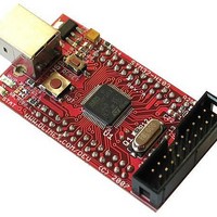
STM32-H103
Description
MCU, MPU & DSP Development Tools HDR BRD FOR STM32F103RBT6
Manufacturer
Olimex Ltd.
Datasheet
1.STM32-H103.pdf
(17 pages)
Specifications of STM32-H103
Processor To Be Evaluated
STM32F103RBT6
Data Bus Width
32 bit
Interface Type
USB, CAN, I2C, JTAG, SPI, UART
Dimensions
61 mm x 34 mm
Operating Supply Voltage
3.3 V
Core Architecture
ARM
Cpu Core
ARM Cortex M3
Lead Free Status / RoHS Status
Lead free / RoHS Compliant
Available stocks
Company
Part Number
Manufacturer
Quantity
Price
Company:

Part Number:
STM32-H103
Manufacturer:
Olimex Ltd.
Quantity:
135


INPUT/OUTPUT:
JTAG:
TMS
TCK
TDI
TDO
TRST
Input
Input
Input
Output Test Data Output. This is the serial data output from the shift register. Data is shifted out of the
Input
Test Mode Select. The TMS pin selects the next state in the TAP state machine.
Test Clock. This allows shifting of the data in, on the TMS and TDI pins.
It is a positive edgetriggered clock with the TMS and TCK signals that define the internal state
of the device.
Test Data In. This is the serial data input for the shift register.
device on the negative edge of the TCK signal.
Test Reset. The TRST pin can be used to reset the test logic within the EmbeddedICE logic.
User button with name BUT – connected to STM32F103RBT6 pin.14
PA0.WKUP;
Status green LED with name STAT connected to STM32F103RBT6 pin.53
PC12, note that LED-E SMT jumper should be shorted to may LED work
properly (it’s shorted by default), if you decide to use PC12 port for other
purpose you have to remove the solder short on this jumper which will
disconnect the LED from PC12 port;
Power supply red LED with name PWR – indicates that 3.3V power supply
is applied;
The JTAG connector allows the software debugger to talk via a JTAG (Joint
Test Action Group) port directly to the core. Instructions may be inserted and
executed by the core thus allowing
programmed with code and executed step by step by the host software.
For more details refer to IEEE Standard 1149.1 - 1990 Standard Test Access
Port and Boundary Scan Architecture and
users manual.
JTAG CONNECTOR PIN DESCRIPTIONS
1
3
5
7
9
11
13
15
17
19
Pin #
TVCC 3.3V
TRST
TDI
TMS
TCK
NC
TDO
RST
NC
NC
Signal Name
STM32F103RBT6
2
4
6
8
10
12
14
16
18
20
STM32F103RBT6
Pin #
TVCC 3.3V
GND
GND
GND
GND
GND
GND
GND
GND
GND
Signal Name
memory to be
datasheets and
Related parts for STM32-H103
Image
Part Number
Description
Manufacturer
Datasheet
Request
R

Part Number:
Description:
MCU, MPU & DSP Development Tools HDR BRD FOR STM32F103RBT6
Manufacturer:
Olimex Ltd.
Datasheet:

Part Number:
Description:
MCU, MPU & DSP Development Tools STARTERKIT BRD FOR STM32F103RBT6
Manufacturer:
Olimex Ltd.
Datasheet:

Part Number:
Description:
Development Boards & Kits - ARM PROTOTYPE BRD STM32F407
Manufacturer:
Olimex Ltd.
Part Number:
Description:
Development Boards & Kits - ARM PROTOTYPE BRD STM32F207
Manufacturer:
Olimex Ltd.
Part Number:
Description:
Microcontroller Modules & Accessories PROTOTYPE BOARD FOR STM32F107VCT6
Manufacturer:
Olimex Ltd.
Part Number:
Description:
MCU, MPU & DSP Development Tools HEADER BOARD FOR STM32F107
Manufacturer:
Olimex Ltd.
Part Number:
Description:
Development Boards & Kits - ARM DEVELOPMENT BOARD STM32F407ZGT6
Manufacturer:
Olimex Ltd.
Part Number:
Description:
Development Boards & Kits - ARM DEVELOPMENT BOARD STM32F407ZGT6
Manufacturer:
Olimex Ltd.
Part Number:
Description:
Development Boards & Kits - ARM PROTOTYPE BRD STM32L152VBT6
Manufacturer:
Olimex Ltd.
Part Number:
Description:
Development Boards & Kits - ARM HDR BOARD FOR STM32L152VBT6
Manufacturer:
Olimex Ltd.

Part Number:
Description:
Microcontroller & Microprocessor Development Tools TCP-IP DEV BRD PIC32MX460F512
Manufacturer:
Olimex Ltd.
Datasheet:

Part Number:
Description:
Microcontroller & Microprocessor Development Tools PROTOTYPE BOARD TMS320F28027
Manufacturer:
Olimex Ltd.
Datasheet:

Part Number:
Description:
Microcontroller & Microprocessor Development Tools HDR BRD FOR LPC3131
Manufacturer:
Olimex Ltd.
Datasheet:

Part Number:
Description:
Microcontroller & Microprocessor Development Tools MP3 PLYR MOD WITH VS1002
Manufacturer:
Olimex Ltd.
Datasheet:
Part Number:
Description:
Microcontroller & Microprocessor Development Tools MP3 PLYR MOD BAT WITH VS1002
Manufacturer:
Olimex Ltd.
Datasheet: