M1AFS-ADV-DEV-KIT-PWR Actel, M1AFS-ADV-DEV-KIT-PWR Datasheet
M1AFS-ADV-DEV-KIT-PWR
Specifications of M1AFS-ADV-DEV-KIT-PWR


Related parts for M1AFS-ADV-DEV-KIT-PWR

M1AFS-ADV-DEV-KIT-PWR Summary of contents
Page 1
Fusion Advanced Development Kit User’s Guide ...
Page 2
... This document contains confidential proprietary information that is not to be disclosed to any unauthorized person without prior written consent of Actel Corporation. Trademarks Actel, IGLOO, Actel Fusion, ProASIC, Libero, Pigeon Point and the associated logos are trademarks or registered trademarks of Actel Corporation. All other trademarks and service marks are the property of their respective owners. ...
Page 3
... Hooking up the Board and Programming Stick . . . . . . . . . . . . . . . . . . . . . . . . . . 55 Hooking Up the Board and Ethernet Cable . . . . . . . . . . . . . . . . . . . . . . . . . . . . 56 Programming the Board . . . . . . . . . . . . . . . . . . . . . . . . . . . . . 57 Setting Up the Test Terminal . . . . . . . . . . . . . . . . . . . . . . . . . . . . . . . . . . . 60 Running the M1AFS-ADV-DEV-KIT Board Test . . . . . . . . . . . . . . . . . . 66 M1AFS-ADV-DEV-KIT Board Failures . . . . . . . . . . . . . . . . . . . . . . . . . . . . . 87 D Product Support . . . . . . . . . . . . . . . . . . . . . . . . . . . . . . . . . . 89 Actel Customer Technical Support Center . . . . . . . . . . . . . . . . . . . . . . . . . . . . . 89 Actel Technical Support . . . . . . . . . . . . . . . . . . . . . . . . . . . . . . . . . . . . . . 89 Website . . . . . . . . . . . . . . . . . . . . . . . . . . . . . . . . . . . . . . . . . . . . . . . 89 Contacting the Customer Technical Support Center . . . . . . . . . . . . . . . . . . . . . . . . 89 Index . . . . . . . . . . . . . . . . . . . . . . . . . . . . . . . . . . . . . . . 91 Fusion Advanced Development Kit User’ ...
Page 4
...
Page 5
... Fusion Advanced Development Kit User’s Guide ™ -M1–based systems Navigation-Style Legacy Push Switches Connector OLED DIP SPI Flash Display Switches Memory M1AFS1500- Current MPM Area FGG484 Sensor Figure 1 · Fusion Advanced Development Kit SRAM / Flash Memories RealView Header Interface Header Power ...
Page 6
... M1FAS-ADV-DEV-KIT does not include power supplies, so for this kit you must also order two of the 9V POWER PACKs. M1AFS-ADV-DEV-KIT-PWR includes the two power packs. Fusion Advanced Development Kit Web Resources For further kit information, including user's guides, tutorials, and full design examples, refer to the Fusion Advanced Development Kit page: www ...
Page 7
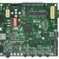
Power Supply Regulator RV5 Potentiometer OLED Rail Voltage Readout Switch (SW2) Output D1 - D12 LED Indicators Power Supply Regulator REG1 - REG4 Interrupt Switches (SW8, SW11, SW16, SW15) Figure 2 · Fusion Advanced Development Kit Board for Mixed-Signal Power ...
Page 8
... Mixed-signal header for several daughter boards to be attached for extended mixed-signal applications The board includes a programming stick header so the LCPS can be attached to the board for programming. Table 2 describes the Fusion Advanced Development Kit board components. Name M1AFS1500-FGG484 PWM CIRCUIT POT CIRCUIT CURRENT SENSING TEMP MONITOR DIODE ...
Page 9
Table 2 · Fusion Advanced Development Kit Board Components (continued) Name SRAM FLASH SPI FLASH PROG HDR MIXED_CONN40 LC_JTAG Table 3 describes the Mixed-Signal Power Manager board components. Component MPM_REG1_3P3 MPM_REG2_1P5 MPM_REG3_5V MPM_REG4_5V RV1, RV2, RV3, RV4 SW8, SW11, SW15, ...
Page 10
...
Page 11
... Hardware Installation The FlashPro3 programmer is built into the low-cost programming stick (LCPS) and plugs directly into the FADK board. The USB 2.0 high-speed cable plugs into the LCPS to allow the M1AFS1500 device to be programmed. Jumper and Switch Settings Recommended default jumper settings are defined in default settings to enable the pre-programmed demonstration design to function correctly ...
Page 12
... However, this enable pin is also connected to the pin on the Fusion FPGA (MPM_REG1_EN, MPM_REG2_EN, MPM_REG3_EN, MPM_REG4_EN). The FPGA would be damaged if it were driven High on the enable line and grounded at the same time. To avoid this, Actel recommends that the FPGA pin driving these enable pins is set to Low or tristate. ...
Page 13
Table 1-5 and Table 1-6 Test Point TP3 9 V input TP4 1.5 V supply rail TP7 3.3 V supply rail TP8 3.3 V supply AFS TP10 10 V rail for OLED TP19 3.3 V voltage and current sensing circuit ...
Page 14
... Installation and Settings Testing the Hardware If the board is shipped directly from Actel, it contains a test program that determines whether the board works properly. If while using the board you suspect that the board is damaged, you can rerun the verify the key components of the board functionality . ...
Page 15
... Hardware Components FPGA Description and Connections The Fusion Advanced Development Kit board is populated with an M1-enabled Fusion M1AFS1500 FPGA. The key features of the M1AFS1500 device are listed below: • High-performance reprogrammable flash technology • Embedded flash memory • Integrated A/D converter (ADC) and Analog Quad • ...
Page 16
... Actel Libero IDE, optimized for Actel FPGA architecture, and supplied with a complete toolset for code compile and debug. The Fusion Advanced Development Kit board contains a Fusion M1AFS1500 FPGA device, which is Cortex-M1– enabled. Cortex-M1 is the first ARM processor developed specifically for implementation in FPGAs. In addition to Cortex M1, this Fusion FPGA can be programmed with Core8051(s) or CoreABC ...
Page 17
... All Enable pins to the regulator are active High. Note: For more information about the MPM circuit functionality and a design example for the MPM GUI, refer Mixed- Signal Power Management Quickstart Guide: www.actel.com/documents/MixedSignal_Power_Manager_QS.pdf. Fusion Advanced Development Kit User’s Guide Mixed-Signal Power Management ...
Page 18
Hardware Components Board Components for Power Management 3.3 V Power Supply, MPM_REG1_3P3, National LM3100MH This regulated switching mode power supply can deliver output current with regulated output voltage from 0.8 to 5.0 VDC, over a ...
Page 19
V Power Supply, MPM_REG2_1P5, National LP38693-ADJ This is a low drop-out voltage regulator (250 mV at 500 mA with 5 V o/p) with output voltage ranging from 1. The input has a wide range from ...
Page 20
Hardware Components 5 V Power Supply 1, MPM_REG3_5V, Lineage Power ATA010A0X43 The 12 V single in-line package (SIP) power module can deliver output current with regulated output voltage from 0.75 to 5.0 VDC, over a ...
Page 21
V Power Supply 2, MPM_REG4_5V, Linear Technology LTM 4602 This DC/DC converter can deliver output current with regulated output voltage from 0.6 to 5.0 VDC, over a wide range of input voltage (V between ...
Page 22
... These voltage waveforms can be displayed on the OLED or used via the mixed-signal header. In addition, one PWM RC circuit source is routed to the AV input pin of an analog quad. This AV pin can be used to monitor the generated voltage with high accuracy, depending on the ADC resolution configured in the FPGA. Mfr P/N : M1AFS1500-FGG484 Mfr: Actel Potentiometer Circuit A potentiometer circuit potentiometer circuit is connected to the AC input pin, which can be used to monitor voltage ...
Page 23
Current Sensing Circuit For current monitor applications, two current sensing circuits are provided on the Fusion Advanced Development Kit board. One of the current sensing circuits is for the 3.3 V voltage rail rail (Figure 2-9) of the Fusion FPGA. ...
Page 24
Hardware Components MOSFET for the Gate Driver Block Two external p-channel MOSFETs are populated on the board, connected to the AG pins of the Fusion Analog Quad. One MOSFET is connected on the 3.3 V voltage rail Fusion FPGA (Figure ...
Page 25
Clock Oscillator A 50 MHz clock oscillator with 50 ppm is available on the board FPGA to provide a system or reference clock. An on-chip Fusion PLL can be configured and instantiated in the FPGA to generate a wide range ...
Page 26
Hardware Components Crystal Oscillator A 32.768 KHz off-chip crystal oscillator with 50 ppm is populated on the board. The off-chip crystal oscillator is connected to the digital XTAL1 and XTAL2 (on-chip crystal oscillator) inputs of the Fusion FPGA. The on-chip ...
Page 27
Push-Button System Reset A push-button system reset switch with a Schmitt trigger is provided on the board reduces noise on the system reset push-button. V3P3 VCC 3 GND DS1818 DS1818 Mfr P/N :DS1818R-10+T&R Mfr: Dallas s; need ...
Page 28
Hardware Components Push-Button Switches and User LEDs Push-button switches and user LEDs can also be used for debug and for various applications, such as gaming ((Figure 2-17 and Figure SW2 SW2 1 3 EVQ-PAD04M EVQ-PAD04M Mfr P/N :EVQ-PAD04M Panasonic - ...
Page 29
The FADK also contains a 8-position DIP switch bank for general purpose use. All signals are connected to the FPGA. The LEDs and switches are active High and the switches have 10-K pull-down resistors. You can also utilize any unused ...
Page 30
... Any standard I2C controller can be implemented or instantiated in the Fusion FPGA to allow communication with the I2C interface. In addition, the Actel IP catalog includes various programmable I2C controllers, specifically CoreI2C, with an APB interface that can be instantiated in the FPGA design with a Cortex-M1 embedded processor. The CoreI2C controller supports both Master and Slave modes with configurable parameters for various applications ...
Page 31
OLED Display A 96×16-pixel low-power OLED is available on the board for display. This low-power device, BLUE OLED, requires 3.3 V and 10 V power supplies. By default, the OLED supports the I2C, but it can also support an SPI ...
Page 32
Hardware Components Interface Connector A standard interface connector on the board can be used to extend this development kit to connect with additional daughter cards, some of which are developed by partners and third party vendors possibilities are numerous, such ...
Page 33
... M1-enabled Fusion FPGA, serves many purposes. For example, this interface can be used to access the Fusion FPGA to monitor the ADC data over a network control registers can be accessed and processed remotely to support system management. The Actel IP catalog includes a Core10100 Ethernet MAC with Host Controller. ...
Page 34
Hardware Components 34 AVDD33 22 IOVDD33_2 48 IOVDD33_1 32 Figure 2-26 · Ethernet Interface Schematic Fusion Advanced Development Kit User’s Guide VDD GND 4 2 ...
Page 35
... USB-to-UART bridge controller (U6) to provide a standard UART connection with the Fusion FPGA. Any standard UART controller can be implemented in the Fusion FPGA to allow access with this interface. In addition, the Actel IP catalog includes various UART controllers, specifically CoreUARTapb, with an AMBA APB interface that can be instantiated in the FPGA with a Cortex-M1 embedded processor. The programmable CoreUARTapb controller supports both asynchronous and synchronous modes with configurable parameters for various applications ...
Page 36
... Flash memory in the Fusion FPGA, these on-board SRAMs extend the memory space of the system and can be easily accessed by an embedded processor, such as Cortex-M1 embedded processor system, these on-board SRAM can be accessed by a standard memory controller, such as CoreMemCtrl (available from Actel's IP catalog). V3P3 U20 ...
Page 37
... Cortex-M1 embedded microprocessor to access additional memory off-chip peripheral interface (SPI synchronous serial data link standard embedded microprocessor system, CoreSPI (available from Actel's IP catalog) can be instantiated to communicate with the SPI flash. Some advantages of the SPI interface are full duplex communication and higher throughput than I2C. ...
Page 38
... DIRECTC_TCK {5} DIRECTC_TDO {5} DIRECTC_TMS {5} DIRECTC_TRST {5} DIRECTC_TDI VPUMP/VJTAG Configuration Connected to 3.3 V Not connected (powers through FP3) 38 (Figure 2-31). Table 2-3 Low-Cost SYS MAN M1AFS1500 DirectC Header Figure 2-31 · DirectC Programming of Another Board J16 J16 1 TCK 3 TDO 5 TMS 8 TRST 9 TDI DIRECT_C DIRECT_C Mfr P/N :HTST-105-01-L-DV-A Mfr: Samtec Inc Figure 2-32 · ...
Page 39
Mixed-Signal Header A range of Fusion mixed-signal pins, particularly the analog AV, AC, AG, and AT pins of the Analog Quad and GPIO I/O pins, is available on the mixed-signal header on this board daughter boards to access the Fusion ...
Page 40
Hardware Components Low-Cost Programming Stick The Fusion Advanced Development Kit board can be programmed using the low-cost programming stick (LCPS). The LCPS is a special version of the FlashPro3 programming circuitry that is compatible with FlashPro3 and the generic FlashPro ...
Page 41
... TCK VJTAG TDI U17 Y22 TDI VPUMP TMS V18 TMS V22 TDO TRST V21 TRST R54 R54 R55 R55 AFS1500 AFS1500 Mfr P/N : AFS600 Mfr: Actel 510_NL 510_NL 1K 1K JTAG HEADER J6 J6 R112 R112 TCK 1 2 TDO TMS VJTAG 5 6 VPUMP ...
Page 42
...
Page 43
... Pin List Table A-1 lists the Fusion M1AFS1500 pin list and I/O pins connections. M1AFS1500 Pin Number E19 E22 F20 F21 F22 B18 B17 C16 B15 B14 C22 C21 A18 A17 A16 B12 A12 A13 A14 A15 C14 C13 D12 J7 D19 ...
Page 44
... K20 J21 K22 H21 M22 M19 L21 K19 J22 J20 H22 G22 Table A-1 · FPGA Pin List (continued) M1AFS1500 Pin Name IO34NDB1V1 IO30PDB1V1 IO47NPB2V0 GBB0/IO41NDB1V2 IO38NPB1V2 IO36PPB1V2 IO34PDB1V1 IO28PDB1V1 IO32PPB1V1 IO30NDB1V1 GCB0/IO63NDB2V0 IO69NDB2V0 GCA1/IO64PDB2V0 GCC1/IO62PDB2V0 IO61NDB2V0 IO55PSB2V0 IO56NDB2V0 IO54NDB2V0 GCB1/IO63PDB2V0 ...
Page 45
... J16 Fusion Advanced Development Kit User’s Guide Table A-1 · FPGA Pin List (continued) M1AFS1500 Pin Name GFB1/IO106PDB4V0 GFC0/IO107NDB4V0 IO115NDB4V0 IO52PDB2V0 IO70NDB2V0 IO68PPB2V0 IO123NDB4V0 IO114PDB4V0 GAA0/IO01NDB0V0 GAA1/IO01PDB0V0 GAC0/IO03NDB0V0 IO05NDB0V1 IO10NDB0V1 IO09NDB0V1 IO04PDB0V0 IO07NDB0V1 IO09PDB0V1 IO06NDB0V1 GAC1/IO03PDB0V0 IO05PDB0V1 IO08PDB0V1 IO12NDB0V1 IO07PDB0V1 ...
Page 46
... F19 L18 K17 L16 G13 H17 D13 J17 E12 AB3 Table A-1 · FPGA Pin List (continued) M1AFS1500 Pin Name GFA0/IO105NDB4V0 IO108NDB4V0 GFC2/IO108PDB4V0 IO102PDB4V0 IO101PDB4V0 IO109NDB4V0 IO00PDB0V0 IO00NDB0V0 GAA2/IO125PDB4V0 GAC2/IO123PDB4V0 IO86NDB4V0 IO14PDB0V2 IO45NDB2V0 IO49NDB2V0 IO69PDB2V0 IO58PDB2V0 IO70PDB2V0 IO28NDB1V1 IO53NDB2V0 IO32NPB1V1 IO58NDB2V0 ...
Page 47
... R22 R21 W22 R18 T16 U21 U22 R19 F10 Fusion Advanced Development Kit User’s Guide Table A-1 · FPGA Pin List (continued) M1AFS1500 Pin Name GEA2/IO85PDB4V0 GEC2/IO87PDB4V0 GEB1/IO89PDB4V0 GEC1/IO90PDB4V0 IO98NDB4V0 IO98PDB4V0 IO95NDB4V0 GEC0/IO90NDB4V0 IO84NDB2V0 GBA2/IO44PDB2V0 IO74NDB2V0 IO74PDB2V0 IO43PDB1V2 GDC2/IO84PDB2V0 IO44NDB2V0 ...
Page 48
... B11 B5 A10 E11 D10 G10 T3 H19 P16 P17 P18 P21 N16 N17 P20 P19 48 Table A-1 · FPGA Pin List (continued) M1AFS1500 Pin Name IO100PPB4V0 IO76NPB2V0 IO97NDB4V0 IO97PDB4V0 GAB1/IO02PDB0V0 IO16NDB0V2 IO116PDB4V0 IO116NDB4V0 IO118PDB4V0 IO118NDB4V0 IO16PDB0V2 GAB0/IO02NDB0V0 IO23NDB1V0 IO24PDB1V0 IO11PDB0V1 IO10PDB0V1 IO24NDB1V0 ...
Page 49
... N22 J18 N20 J19 H18 K16 E21 Fusion Advanced Development Kit User’s Guide Table A-1 · FPGA Pin List (continued) M1AFS1500 Pin Name IO72NDB2V0 IO71NDB2V0 IO112NPB4V0 IO92NDB4V0 IO117NDB4V0 IO104PDB4V0 IO99PDB4V0 IO117PDB4V0 IO119NSB4V0 IO121NDB4V0 IO120PDB4V0 IO120NDB4V0 IO122PSB4V0 IO121PDB4V0 IO52NDB2V0 IO71PDB2V0 IO57NDB2V0 ...
Page 50
... M1AFS1500 Pin Number Table A-1 · FPGA Pin List (continued) M1AFS1500 Pin Name IO103PDB4V0 IO103NDB4V0 Fusion Advanced Development Kit User’s Guide Board Signal Name UART_RXD UART_TXD ...
Page 51
FADK Board Stack-Up The Fusion Advanced Development Kit board is built on a 10-layer printed circuit board (PCB). The top and bottom silkscreens are provided Fusion Advanced Development Kit page. To view the PCB design layout files, you can use ...
Page 52
Figure B-1 · Layer 1, Top Silkscreen Fusion Advanced Development Kit User’s Guide ...
Page 53
Fusion Advanced Development Kit User’s Guide Figure B-2 · Layer 10, Bottom Silkscreen 53 ...
Page 54
...
Page 55
... M1AFS-ADV-DEV-KIT board. Hooking up the Board and Programming Stick 1. Connect the Actel M1AFS-ADV-DEV-KIT board to the Actel programming stick. Connect the J1 pins on the M1AFS-ADV-DEV-KIT board to the programmer, as shown in Fusion Advanced Development Kit User’s Guide Figure C-1 · Connect J1 Pins on M1AFS-ADV-DEV-KIT Board Figure C-1 ...
Page 56
... Actel programming stick. These connections are labeled USB 1 and USB Connect the USB cables to the PC you will use for testing. 4. Connect one end power supply to power input, Power1, on the M1AFS-ADV-DEV-KIT board, as seen in Figure C-1 on page outlet. 5. When push-button SW15 is pressed after power-up, LED DM4 should light up. ...
Page 57
Programming the Board 1. Open the FlashPro programming software. 2. Create a new programming project Fusion Advanced Development Kit User’s Guide (Figure C-2). Figure C-2 · New Project Programming the Board 57 ...
Page 58
Manufacturing Test 3. Select the option Single Device when choosing the programming mode 4. Click on the Configure Device button. This opens the Load Programming File window. 58 Figure C-3 · Select Single Device Fusion Advanced Development Kit User’s Guide ...
Page 59
... Browse the PC file system to find the M1AFS-ADV-DEV-KIT.stp programming file. Click Open to select the M1AFS-ADV-DEV-KIT.stp file 6. Click the Program button to program the M1AFS-ADV-DEV-KIT board. Fusion Advanced Development Kit User’s Guide (Figure C-4). Figure C-4 · Load Programming File Programming the Board ...
Page 60
Manufacturing Test Setting Up the Test Terminal 1. Open the Windows start menu. Select All > Programs > Accessories > Communications and select the HyperTerminal program. This opens HyperTerminal 60 (Figure C-5). Figure C-5 · Select HyperTerminal Fusion Advanced Development ...
Page 61
... The Connection Description window will open the new HyperTerminal session and click the OK button. Fusion Advanced Development Kit User’s Guide (Figure C-6). Type in M1AFS-ADV-DEV-KIT as the name of Figure C-6 · Connection Description Window Setting Up the Test Terminal 61 ...
Page 62
Manufacturing Test 3. The Connect To window will open. Select the COM3 serial connection 62 Figure C-7 · Select COM3 Serial Connection Fusion Advanced Development Kit User’s Guide (Figure C-7). ...
Page 63
The COM3 Properties window appears Bits per second = 19200 Data bits = 8 Parity = None Stop bits = 1 Flow Control = None Click the OK button to keep the settings. Fusion Advanced Development Kit User’s Guide ...
Page 64
Manufacturing Test 5. Select File >Properties in the HyperTerminal window. Choose the Settings tab 64 Figure C-9 · HyperTerminal Settings Tab Fusion Advanced Development Kit User’s Guide (Figure C-9). ...
Page 65
Click the ASCII Setup button. Select the check box labeled Append line feeds to incoming line ends Fusion Advanced Development Kit User’s Guide Setting Up the Test Terminal Figure C-10 · ASCII Setup (Figure C-10). 65 ...
Page 66
... Manufacturing Test Running the M1AFS-ADV-DEV-KIT Board Test Note: If the testing environment is not set up correctly, the M1AFS-ADV-DEV-KIT board test will not be possible. Make sure to complete “Programming the Board” on page 57 Procedure 1. Press the button labeled SW1 on the M1AFS-ADV-DEV-KIT board to start the test program. ...
Page 67
... The message shown in If the menu appears correctly, enter the character Y into the terminal. Fusion Advanced Development Kit User’s Guide Running the M1AFS-ADV-DEV-KIT Board Test Figure C-12 should be displayed. Figure C-12 · Reset Test Passed 67 ...
Page 68
Manufacturing Test 5. Enter 1 into the terminal to begin the UART test. Type the character Y into the terminal. The screen shown in Figure C-13 should appear. 68 Figure C-13 · UART Test Passed Fusion Advanced Development Kit User’s ...
Page 69
... Enter 2 into the terminal to begin the Ethernet Test. The screen shown in Note: The IP address field need not be the same for the test to pass. Fusion Advanced Development Kit User’s Guide Running the M1AFS-ADV-DEV-KIT Board Test Figure C-14 Figure C-14 · Ethernet Test Passed should appear. ...
Page 70
Manufacturing Test 7. Enter 3 into the terminal to begin the Analog Test. The screen shown in 8. Locate POT RV5 on the top, left hand corner of the board. Turn POT RV5 counter-clockwise all the way to the left, ...
Page 71
... When done turning the POT, enter Y in the terminal. The screen shown in Fusion Advanced Development Kit User’s Guide Running the M1AFS-ADV-DEV-KIT Board Test Figure C-17 Figure C-17 · Analog Test Passed should appear. 71 ...
Page 72
Manufacturing Test 10. Enter 4 into the terminal to begin the OLED Test. The screen shown in 72 Figure C-18 Figure C-18 · OLED Test Fusion Advanced Development Kit User’s Guide appears. ...
Page 73
... Check the board OLED display. If the Characters “ACTEL” are displayed in the OLED, enter Y in the terminal; otherwise, enter was entered, the screen shown in Fusion Advanced Development Kit User’s Guide Running the M1AFS-ADV-DEV-KIT Board Test Figure C-19 will be displayed. Figure C-19 · OLED Test Passed ...
Page 74
Manufacturing Test 12. Enter 5 into the terminal to begin the RTC Test. After a few seconds, the screen shown in appear. 74 Figure C-20 · RTC Test Passed Fusion Advanced Development Kit User’s Guide Figure C-20 should ...
Page 75
... Enter 6 into the terminal to begin the Memory Test. After several seconds, the screen shown in appear. Fusion Advanced Development Kit User’s Guide Running the M1AFS-ADV-DEV-KIT Board Test Figure C-21 · Memory Test Passed Figure C-21 should 75 ...
Page 76
Manufacturing Test 14. Enter 7 into the terminal to begin the SPI Test. The screen shown in 15. Remove jumpers JP12, JP13, JP14, and JP15 from the board, as shown in the board. 76 Figure C-22 Figure C-22 · SPI ...
Page 77
... Press push-buttons SW8, SW1, SW16, and SW15, as shown in Fusion Advanced Development Kit User’s Guide Figure C-24 · MPM Test – Push-Buttons SW11 SW16 SW15 SW8 Figure C-25 · Press Push-Buttons SW8, SW11, SW16, and SW15 Running the M1AFS-ADV-DEV-KIT Board Test Figure C-24 will appear. Figure C-25. 77 ...
Page 78
Manufacturing Test 18. Enter Y in the terminal when complete. The screen shown in 19. Turn POTs labeled RV1, RV2, RV3, and RV4 clockwise all the way to the right, as shown in 78 Figure C-26 Figure C-26 · MPM ...
Page 79
... Turn POTs labeled RV1, RV2, RV3, and RV4 counter-clockwise all the way to the left, as shown in Fusion Advanced Development Kit User’s Guide Running the M1AFS-ADV-DEV-KIT Board Test Figure C-28 · MPM Test – Replace Jumpers Figure C-29 · Turn POTs RV1 – RV4 Counter-Clockwise Figure C-28 should appear ...
Page 80
Manufacturing Test 22. Enter Y in the terminal when done turning POTs. The terminal screen shown in 80 Figure C-30 · MPM Test – Trimming Fusion Advanced Development Kit User’s Guide Figure C-30 should appear. ...
Page 81
... Press and hold push-button SW8 for 2 seconds. The screen shown in 24. Repeat for the other push-buttons. Fusion Advanced Development Kit User’s Guide Running the M1AFS-ADV-DEV-KIT Board Test Figure C-31 · MPM Test – Trimming, Continued Figure C-31 should appear. 81 ...
Page 82
Manufacturing Test When complete, the screen shown in 82 Figure C-32 should appear. Figure C-32 · MPM Test Passed Fusion Advanced Development Kit User’s Guide ...
Page 83
... Enter 9 into the terminal to begin the LEDs Test. The screen shown in Board LEDs labeled D1, D2, D3, D4, D7, D9, D10, and D11 will blink on and off, as shown in Fusion Advanced Development Kit User’s Guide Running the M1AFS-ADV-DEV-KIT Board Test Figure C-33 · LEDs Test Figure C-34 · LEDs On (left) and LEDs Off (right) Figure C-33 will appear ...
Page 84
Manufacturing Test 26. If you do observe the LEDs blinking, enter Y in the terminal. Otherwise enter was entered, the screen shown in Figure C-35 will be displayed. 84 Figure C-35 · LEDs Test Passed Fusion Advanced ...
Page 85
... Enter A into the terminal to begin the Switches Test. The screen shown in Fusion Advanced Development Kit User’s Guide Running the M1AFS-ADV-DEV-KIT Board Test Figure C-36 Figure C-36 · Begin Switches Test will appear. 85 ...
Page 86
Manufacturing Test 28. Press switches on the board labeled SW1, SW2, SW3, SW4, and SW5. After all switches have been pressed, the screen shown in 29. Flip all DIP switches on the board to the OPEN position, as shown in ...
Page 87
... Test” on page 66, the board being tested is not functional. Put this non-functional board in an area separate from the boards which have passed testing and those which are yet to be tested. Keep these nonfunctional M1AFS-ADV-DEV- KIT boards for further investigation. Fusion Advanced Development Kit User’s Guide Figure C-39 should appear after the switches have been flipped ...
Page 88
...
Page 89
... Fax, from anywhere in the world 650.318.8044 Actel Customer Technical Support Center Actel staffs its Customer Technical Support Center with highly skilled engineers who can help answer your hardware, software, and design questions. The Customer Technical Support Center spends a great deal of time creating application notes and answers to FAQs ...
Page 90
... Pacific Time, Monday through Friday. The Technical Support numbers are 650.318.4460 800.262.1060 Customers needing assistance outside the US time zones can either contact technical support via email (tech@actel.com) or contact a local sales office. 90 Sales office listings can be found at www.actel.com/company/contact/default.aspx. Fusion Advanced Development Kit User’s Guide ...
Page 91
... J JTAG header 41 jumper settings 11 K kit contents 6 L LCPS 40 photograph 40 LEDs 28 LEDs schematic 29 low-cost programming stick (LCPS M1AFS1500 key features 15 mixed-signal header 39 MOSFET 24 MPM 17 , board components 9 18 push-button switches 12 test points 14 N navigation switches 28 O OLED display 31 ...
Page 92
Index OLED display schematic 31 P parallel flash 37 pin list 43 potentiometer circuit 22 power management, mixed-signal 17 power sources 16 power supply 1 3 – product support 89 90 ...
Page 93
...
Page 94
... Phone 650.318.4200 • Fax 650.318.4600 • Customer Service: 650.318.1010 • Customer Applications Center: 800.262.1060 Actel Europe Ltd. • River Court, Meadows Business Park • Station Approach, Blackwater • Camberley Surrey GU17 9AB • United Kingdom Phone +44 (0) 1276 609 300 • Fax +44 (0) 1276 607 540 Actel Japan • ...