MOD-RFID125-BOX Olimex Ltd., MOD-RFID125-BOX Datasheet - Page 6
MOD-RFID125-BOX
Manufacturer Part Number
MOD-RFID125-BOX
Description
RFID Modules & Development Tools RFID RDR FOR 125KHZ TAGS 100x50x10mm
Manufacturer
Olimex Ltd.
Datasheet
1.MOD-RFID125.pdf
(12 pages)
Specifications of MOD-RFID125-BOX
Operating Current
120 mA
Operating Voltage
5 V
Product
RFID Readers
Wireless Frequency
125 KHz
Interface Type
UART
Dimensions
100 mm x 50 mm
Kit Features
USB Plug In Module, Read RFID125 KHz Tags From Up To 5-15 CM Distance, RS232, USB, SPI Interface
Tool Type
Wireless Development Kit
Processor To Be Evaluated
Multiple
Core Architecture
Multiple
Cpu Core
Multiple
Processor Series
Multiple
Lead Free Status / RoHS Status
Lead free / RoHS Compliant
Lead Free Status / RoHS Status
Lead free / RoHS Compliant, Lead free / RoHS Compliant
Other names
1776327 52R3637


UART MODE:
SWITCHING OPERATING MODES:
In this mode there is no need for USB connection. Instead the device must
be connected via TTL-level UART of a microcontroller system of choice. It
expects the peer to be configured with 9600 bps, 8bit character, no parity,
1 stop bit. The communication is otherwise the same as in USB CDC mode,
but there is no need for USB. Again, all entered characters are echoed back.
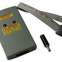
MOD-RFID125's signals RxD and TxD are leaded away to pads, which are
shown at the picture below:
From this side of the board, where is the button, are leaded total five
signals: RxD, TxD, LED1, GND and +5V.
TxD – output from MOD-RFID125
RxD – input for MOD-RFID125
LED1 – doubles LED1 command signal.
GND – Ground
+5V - +5V from USB
The current mode of operation can be selected by pressing and holding the
button of the device. After two seconds the LEDs will start to blink and will
show the code for the next selected mode. When button is released, the
device will reboot and enter the selected mode. Selected mode is
remembered between power downs. The assigned codes are:
Related parts for MOD-RFID125-BOX
Image
Part Number
Description
Manufacturer
Datasheet
Request
R

Part Number:
Description:
RFID Modules & Development Tools RFID RDR FOR 125KHZ TAGS 50x20x5mm
Manufacturer:
Olimex Ltd.
Datasheet:

Part Number:
Description:
RFID Transponder Tools USB RFID READER FOR 13.56MHz TAGS
Manufacturer:
Olimex Ltd.
Datasheet:

Part Number:
Description:
RF Modules & Development Tools GSM WIRELESS PROTOTYPE MODULE
Manufacturer:
Olimex Ltd.
Datasheet:
Part Number:
Description:
RF Modules & Development Tools EDGE WIRELESS PROTOTYPE MODULE
Manufacturer:
Olimex Ltd.
Datasheet:
Part Number:
Description:
RF Modules & Development Tools GSM-B WIRELESS PROTOTYPE MODULE
Manufacturer:
Olimex Ltd.
Datasheet:
Part Number:
Description:
Development Boards & Kits - Wireless USB RFID READER FOR 13.56MHz TAGS
Manufacturer:
Olimex Ltd.

Part Number:
Description:
MOD RF 2.4GHZ 19.2K RS232/485
Manufacturer:
Digi International/Maxstream
Datasheet:
Part Number:
Description:
MOD RF 900MHZ 9600BPS RS232/485
Manufacturer:
Digi International/Maxstream
Datasheet:
Part Number:
Description:
MOD RF 2.4GHZ 9600BPS RS232/485
Manufacturer:
Digi International/Maxstream
Datasheet:

Part Number:
Description:
Microcontroller & Microprocessor Development Tools MP3 PLYR MOD WITH VS1002
Manufacturer:
Olimex Ltd.
Datasheet:
Part Number:
Description:
Microcontroller & Microprocessor Development Tools MP3 PLYR MOD BAT WITH VS1002
Manufacturer:
Olimex Ltd.
Datasheet:

Part Number:
Description:
Microcontroller & Microprocessor Development Tools TCP-IP DEV BRD PIC32MX460F512
Manufacturer:
Olimex Ltd.
Datasheet:

Part Number:
Description:
Microcontroller & Microprocessor Development Tools PROTOTYPE BOARD TMS320F28027
Manufacturer:
Olimex Ltd.
Datasheet:

Part Number:
Description:
Microcontroller & Microprocessor Development Tools HDR BRD FOR LPC3131
Manufacturer:
Olimex Ltd.
Datasheet: