TGA4516 TriQuint, TGA4516 Datasheet
TGA4516
Specifications of TGA4516
Available stocks


Related parts for TGA4516

TGA4516 Summary of contents
Page 1
... The current rises to 1.9A under RF drive. This HPA is ideally suited for many applications such as Military Radar Systems, Ka-band Sat-Com, and Point-to-Point Radios. The TGA4516 is 100% DC and RF tested on-wafer to . ensure performance compliance Lead-Free & RoHS compliant. Datasheet subject to change without notice TriQuint Semiconductor: www ...
Page 2
... For maximum life recommended that junction temperatures be maintained at the lowest possible levels. 6/ These ratings apply to each individual FET. TriQuint Semiconductor: www. triquint.com (972)994-8465 Fax (972)994-8504 Info-mmw@tqs.com May 2009 © Rev - TABLE I VALUE 6 267 mW 12.7 W 200 °C 320 °C -65 to 150 °C TGA4516 NOTES ...
Page 3
... Output Return Loss, S22 Power @ saturated, Psat TriQuint Semiconductor: www. triquint.com (972)994-8465 Fax (972)994-8504 Info-mmw@tqs.com May 2009 © Rev - TABLE II DC PROBE TESTS ( Nominal) MIN. MAX. 80 240 -18 -18 -11 -1.5 -0.5 TABLE III O C, Nominal) TYPICAL 6 1050 TGA4516 UNITS UNITS V mA GHz dBm 3 ...
Page 4
... W with 2 power delivered to load. Power dissipated is 8.2 W and the temperature rise in the channel is 84 °C. Median Lifetime (Tm) vs. Channel Temperature TriQuint Semiconductor: www. triquint.com (972)994-8465 Fax (972)994-8504 Info-mmw@tqs.com May 2009 © Rev - TABLE IV θ Test Conditions C/W) 150 10.2 TGA4516 Tm (HRS) 1E+6 4 ...
Page 5
... Fixtured Performance 25 20 S21 -10 -15 -20 -25 -30 -35 - TGA4516 Pout @ Pin =20dBm Vds=6V, Idq=1050mA TriQuint Semiconductor: www. triquint.com (972)994-8465 Fax (972)994-8504 Info-mmw@tqs.com May 2009 © Rev - Vds=6V, Idq=1050mA S22 S11 Frequency (GHz Fre que ncy (GHz) TGA4516 40 42 Pin=20dBm ...
Page 6
... Fixtured Performance TGA4516 Pout vs. Pin freq=35GHz, Vds=6V, Idq=1050mA 40 Pout Large Signal Gain - TGA4516 Ids vs. Pin freq=35GHz, Vds=6V, Idq=1050mA 40 Pout Ids - TriQuint Semiconductor: www. triquint.com (972)994-8465 Fax (972)994-8504 Info-mmw@tqs.com May 2009 © Rev - Pin (dBm Pin (dBm) TGA4516 2200 2000 1800 1600 ...
Page 7
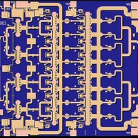
... Output) 0.100 x 0.200 [0.004 x 0.008] (Vd3) 0.100 x 0.200 [0.004 x 0.008] (Vg3) 0.100 x 0.100 [0.004 x 0.004] (Vd12) 0.100 x 0.200 [0.004 x 0.008] (Vg2) 0.100 x 0.100 [0.004 x 0.004] May 2009 © Rev - TGA4516 7 ...
Page 8
... Chip Assembly Diagram GaAs MMIC devices are susceptible to damage from Electrostatic Discharge. Proper precautions should be observed during handling, assembly and test. TriQuint Semiconductor: www. triquint.com (972)994-8465 Fax (972)994-8504 Info-mmw@tqs.com May 2009 © Rev - TGA4516 8 ...
Page 9
... Aluminum wire should not be used. • Maximum stage temperature is 200°C. GaAs MMIC devices are susceptible to damage from Electrostatic Discharge. Proper precautions should be observed during handling, assembly and test. TriQuint Semiconductor: www. triquint.com (972)994-8465 Fax (972)994-8504 Info-mmw@tqs.com Assembly Process Notes May 2009 © Rev - TGA4516 9 ...