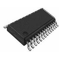
WM8510GEDS/V Wolfson Microelectronics, WM8510GEDS/V Datasheet - Page 14

WM8510GEDS/V
Manufacturer Part Number
WM8510GEDS/V
Description
Audio CODECs VoIP Mono CODEC
Manufacturer
Wolfson Microelectronics
Datasheet
1.WM8510GEDSV.pdf
(82 pages)
Specifications of WM8510GEDS/V
Operating Supply Voltage
- 0.3 V to + 7 V
Maximum Operating Temperature
+ 85 C
Mounting Style
SMD/SMT
Package / Case
SSOP-28
Minimum Operating Temperature
- 25 C
Lead Free Status / RoHS Status
Lead free / RoHS Compliant
WM8510
INPUT SIGNAL PATH
w
AUDIO INTERFACES
The WM8510 has a standard audio interface, to support the transmission of audio data to and from
the chip. This interface is a 4 wire standard audio interface which supports a number of audio data
formats including I
operate in master or slave modes.
CONTROL INTERFACES
To allow full software control over all its features, the WM8510 offers a choice of 2 or 3 wire MPU
control interface. It is fully compatible and an ideal partner for a wide range of industry standard
microprocessors, controllers and DSPs. The selection between 2-wire mode and 3-wire mode is
determined by the state of the MODE pin. If MODE is high then 3-wire control mode is selected, if
MODE is low then 2-wire control mode is selected.
In 2 wire mode, only slave operation is supported, and the address of the device is fixed as 0011010.
CLOCKING SCHEMES
WM8510 offers the normal audio DAC clocking scheme operation, where 256fs MCLK is provided to
the DAC/ADC.
However, a PLL is also included which may be used to generate the internal master clock frequency
in the event that this is not available from the system controller. This PLL uses an input clock,
typically the 12MHz USB or ilink clock, to generate high quality audio clocks. If this PLL is not
required for generation of these clocks, it can be reconfigured to generate alternative clocks which
may then be output on the CSB/GPIO pin and used elsewhere in the system.
POWER CONTROL
The design of the WM8510 has given much attention to power consumption without compromising
performance. It operates at low supply voltages, and includes the facility to power off any unused
parts of the circuitry under software control, includes standby and power off modes.
The WM8510 has 3 flexible analogue inputs for two separate microphone inputs. These inputs can
be used in a variety of ways. The input signal path before the ADC has a flexible PGA block which
then feeds into a gain boost/mixer stage.
MICROPHONE INPUTS
The WM8510 can accommodate a variety of microphone configurations including single ended and
pseudo-differential inputs.
amplified through the input PGA as shown in Figure 6.
A pseudo differential input is the preferential configuration where the positive terminal of the input
PGA is connected to the MICP input pin by setting MICP2INPPGA=1. The microphone ground
should then be connected to MICN (when MICN2INPPGA=1) or optionally to MIC2 (when
MIC2_2INPPGA=1) input pins.
Alternatively a single ended microphone can be connected to the MICN input with MICN2INPPGA set
to 1. The non-inverting terminal of the input PGA should be connected internally to VMID by setting
MICP2INPPGA to 0.
2
S, DSP Mode, MSB-First, left justified and MSB-First, right justified, and can
The inputs through the MICN, MICP and optionally MIC2 pins are
PD, Rev 4.5 ,September 2008
Production Data
14


