CD2320-B1600 Bourns Inc., CD2320-B1600 Datasheet

Bridge Rectifiers Bridge Rectifier 600VOLT

CD2320-B1600

Manufacturer Part Number
CD2320-B1600
Description
Bridge Rectifiers Bridge Rectifier 600VOLT
Manufacturer
Bourns Inc.
Datasheet

Specifications of CD2320-B1600

Product
Single Phase Bridge
Peak Reverse Voltage
600 V
Maximum Rms Reverse Voltage
420 V
Max Surge Current
30 A
Forward Voltage Drop
1 V
Maximum Reverse Leakage Current
5 uA
Maximum Operating Temperature
+ 175 C
Length
5.4 mm
Width
5.9 mm
Height
1.3 mm
Mounting Style
SMD/SMT
Minimum Operating Temperature
- 55 C
Package / Case
SMD/SMT
Lead Free Status / RoHS Status
Lead free / RoHS Compliant
The markets of portable communications, computing and video equipment are challenging the semiconductor industry to develop
increasingly smaller electronic components.
Bourns offers Bridge Rectifier Diodes for rectification applications, in compact chip package 2320 size format, which offer PCB real estate
savings and are considerably smaller than most competitive parts. The Bridge Rectifier Diodes offer a forward current of 1 A with a choice of
repetitive peak reverse voltages between 200 V and 1000 V.
Notes:
1 Measured @ 1.0 MHz and applied reverse voltage of 4.0 VDC.
2 Thermal resistance from junction to ambient and from junction to lead P.C.B. mounted on 0.2 ˝ x 0.2 ˝ (5.0 mm x 5.0 mm) copper pad areas.
*RoHS Directive 2002/95/EC Jan 27, 2003 including Annex.
Specifications are subject to change without notice.
Customers should verify actual device performance in their specific applications.
Electrical Characteristics (@ T A = 25 °C Unless Otherwise Noted)
Thermal Characteristics (@ T A = 25 °C Unless Otherwise Noted)
Parameter
Operating Temperature Range
Storage Temperature Range
General Information
Parameter
Maximum Repetitive
Peak Reverse Voltage
Maximum RMS Voltage
Maximum DC Blocking Voltage
Maximum Average Forward
Rectified Current (T A = 55 °C)
DC Reverse Current @ Rated DC
Blocking Voltage (@T J = 25 °C)
DC Reverse Current @ Rated DC
Blocking Voltage (@T J = 150 °C)
Typical Junction Capacitance
Maximum Instantaneous
Forward Voltage @ 1 A
Typical Thermal Resistance
Peak forward surge current 8.3 ms
single half sine-wave superimposed
on rated load (JEDEC Method)
2
1
CD2320-B1200~B11000 Surface Mount Bridge Rectifier Diode
Symbol
V RRM
Features
V RMS
I FSM
R θJL
V DC
I (AV)
C J
V F
I R
I R
RoHS compliant*
Low power loss & high efficiency
High current capability
Low profile package
Symbol
T
T
STG
J
B1200
200
140
200
B1400
400
280
400
CD2320-B1200~B11000
CD2320-
-55 to +175
-55 to +175
B1600
600
420
600
200
110
1.0
25
30
5
1
Applications
AC operated products
Computer monitors
Set top boxes
Cable modems
B1800
800
560
800
B11000
1000
1000
700
Unit
°C
°C
°C/W
Unit
µA
µA
pF
A
A
V
V
V
V

Related parts for CD2320-B1600

CD2320-B1600 Summary of contents

Page 1

... Customers should verify actual device performance in their specific applications. Features ■ RoHS compliant* ■ Low power loss & high efficiency ■ High current capability ■ Low profile package CD2320-B1200~B11000 Surface Mount Bridge Rectifier Diode CD2320- Symbol B1200 B1400 V RRM 200 400 V RMS 140 ...

Page 2

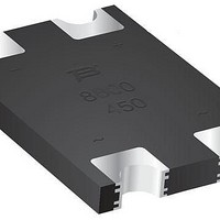
... CD2320-B1200~B11000 Surface Mount Bridge Rectifier Diode Product Dimensions This is a lead free product, packaged with FRP substrate and is epoxy underfilled. The terminals are pure tin plated (lead free) and are solderable per MIL-STD-750, Method 2026. The package weighs approximately 0.07 g. The package and dimensions are shown below. ...

Page 3

... CD2320-B1200~B11000 Surface Mount Bridge Rectifier Diode Rating and Characteristic Curves Forward Current Derating Curve 1.2 1.0 0.8 0.6 0.4 0 Resistive or Inductive Load 100 Ambient Temperature (°C) Forward Characteristics 10.00 1.00 0.10 Pulse Width = 300 µS 0.01 0.2 0.4 0.6 0.8 1.0 ...

Page 4

... CD2320-B1200~B11000 Surface Mount Bridge Rectifier Diode Packaging Information The surface mount product is packaged tape and reel format per EIA-481 standard Index Hole Trailer Device ....... ....... ....... ....... End ....... ....... 10 pitches (min.) Item Symbol Carrier Width A Carrier Length B Carrier Depth C Sprocket Hole d Reel Outside Diameter D Reel Inner Diameter ...

Related keywords