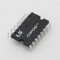
IGCM15F60GA Infineon Technologies, IGCM15F60GA Datasheet

IGCM15F60GA
Specifications of IGCM15F60GA
Available stocks
Related parts for IGCM15F60GA
IGCM15F60GA Summary of contents
Page 1
™ ...
Page 2
... CIPOS™ IGCM15F60GA Revision History: 2010-08 Previous Version: Datasheet Ver. 1.0 Page Subjects (major changes since last revision FLTCLR Authors: Junho Song, Junbae Lee and Daewoong Chung Edition 2010-07 Published by LS Power Semitech Co., Ltd. Seoul, Korea © LS Power Semitech Co., Ltd. All Rights Reserved. ...
Page 3
... P (Positive bus input voltage, Pin 23) ..........................................................................................................7 Absolute Maximum Ratings ............................................................................................................................. 8 Module Section ............................................................................................................................................ 8 RC-IGBT Section .......................................................................................................................................... 8 Control Section ............................................................................................................................................ 8 Recommended Operation Conditions ............................................................................................................ 9 Static Parameters............................................................................................................................................ 10 Dynamic Parameters ...................................................................................................................................... 11 Bootstrap Parameters .................................................................................................................................... 11 Thermistor ...................................................................................................................................................... 12 Mechanical Characteristics and Ratings ...................................................................................................... 12 Circuit of a Typical Application ..................................................................................................................... 13 Switching Times Definition ............................................................................................................................ 13 Package Outline .............................................................................................................................................. 14 Data Sheet CIPOS™ IGCM15F60GA 3/14 Aug. 2010 ...
Page 4
... CIPOS™ IGCM15F60GA CIPOS™ Control Integrated POwer System Dual In-Line Intelligent Power Module 3Φ-bridge 600V / 15A Features Fully isolated Dual In-Line molded module Infineon reverse conducting monolithic body diode Rugged SOI gate driver technology with stability against transient and negative voltage ...
Page 5
... RBS2 VS2 HO3 VB3 VS3 RBS3 LO1 HIN1 HIN2 HIN3 LIN1 LO2 LIN2 LIN3 VDD VFO LO3 ITRIP VSS Thermistor 5/14 CIPOS™ IGCM15F60GA (24) NC (23) P (22) U (21) V (20) W (19) NU (18) NV (17 (24) P (23) U (22) V (21) W (20) NU (19) NV (18) NW (17) Aug. 2010 ...
Page 6
... CIPOS™ IGCM15F60GA Pin Assignment Pin Number Pin Name 1 VS(U) U-phase high side floating IC supply offset voltage 2 VB(U) U-phase high side floating IC supply voltage 3 VS(V) V-phase high side floating IC supply offset voltage 4 VB(V) V-phase high side floating IC supply voltage 5 VS(W) W-phase high side floating IC supply offset voltage ...
Page 7
... P (Positive bus input voltage, Pin 23) The high side IGBT are connected to the bus voltage recommended that the bus voltage does not exceed 400 V. 7/14 CIPOS™ IGCM15F60GA = 12.1V and a BSUV+ = 10.4V. DDUV- of each phase leg ...
Page 8
... CIPOS™ IGCM15F60GA Absolute Maximum Ratings (V = 15V and T = 25°C, if not stated otherwise Module Section Description Storage temperature range Insulation test voltage Operating case temperature range RC-IGBT Section Description Max. blocking voltage Output current Maximum peak output current Short circuit withstand time ...
Page 9
... Control supply variation Logic input voltages LIN,HIN,ITRIP Between VSS - N (including surge) Figure 6: T measurement point C Data Sheet -potential unless otherwise specified. SS Symbol Δ V BS, Δ ITRIP V SS 9/14 CIPOS™ IGCM15F60GA Value Unit min typ max 0 - 400 V 13.5 - 18.5 V 14 V/µ ...
Page 10
... CIPOS™ IGCM15F60GA Static Parameters (V = 15V and T = 25°C, if not stated otherwise Description Collector-Emitter saturation voltage Emitter-Collector forward voltage Collector-Emitter leakage current Logic "1" input voltage (LIN,HIN) Logic "0" input voltage (LIN,HIN) ITRIP positive going threshold ITRIP input hysteresis V and V supply under voltage ...
Page 11
... J 150° 300V 10A 25°C J 150°C Condition Symbol V RRM =25°C J =25° BS1 =125°C J =125° rr_BS V F_BS . BS1 11/14 CIPOS™ IGCM15F60GA Value min typ max - 600 - d(on 750 - d(off 150 - 1450 - SCP 530 290 - FILIN 40 ...
Page 12
... CIPOS™ IGCM15F60GA Thermistor Description Resistor B-constant of NTC (Negative temperature coefficient) Mechanical Characteristics and Ratings Description Mounting torque Flatness Weight Figure 7: Flatness measurement position Data Sheet Condition Symbol T = 25°C R NTC NTC B(25/100) Condition min M3 screw and washer 0.59 Refer to Figure 7 ...
Page 13
... LIN(W) LIN3 (13) VDD VDD (14) VFO VFO LO3 (15) ITRIP ITRIP (16) VSS VSS Thermistor U-phase current sensing V-phase current sensing W-phase current sensing 2. d(off) f d(on) 90% 10% 10% 10% 13/14 CIPOS™ IGCM15F60GA NC (24) P (23) U (22 (21) 3-ph AC Motor W (20) NU (19) NV (18) NW (17 90% Aug. 2010 ...
Page 14
... CIPOS™ IGCM15F60GA Package Outline Data Sheet 14/14 Aug. 2010 ...


