PN4393 Fairchild Semiconductor, PN4393 Datasheet
PN4393
Specifications of PN4393
Available stocks


Related parts for PN4393


PN4393 Summary of contents
Page 1
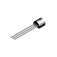
... PN4391 PN4392 PN4393 N-Channel Switch This device is designed for low level analog switching, sample and hold circuits and chopper stabalized amplifiers. Sourced from Process 51. See J111 for characteristics. Absolute Maximum Ratings* Symbol V Drain-Gate Voltage DG V Gate-Source Voltage GS I Forward Gate Current ...
Page 2
Electrical Characteristics Symbol Parameter OFF CHARACTERISTICS V Gate-Source Breakdown Voltage (BR)GSS I Gate Reverse Current GSS V Gate-Source Cutoff Voltage GS(off) V Gate-Source Forward Voltage GS(f) I Drain Cutoff Leakage Current D(off) ON CHARACTERISTICS I Zero-Gate Voltage Drain Current* DSS ...
Page 3
... PROELECTRON SERIES), 96 L34Z TO-92 STANDARD NO LEADCLIP STRAIGHT FOR: PKG 94 (PROELECTRON SERIES BCXXX, BFXXX, BSRXXX), 97, 98 FSCINT Label ©2001 Fairchild Semiconductor Corporation TAPE and REEL OPTION See Fig 2.0 for various Reeling Styles 5 Reels per Intermediate Box F63TNR Label Customized Label AMMO PACK OPTION See Fig 3 ...
Page 4
TO-92 Tape and Reel Data, continued TO-92 Reeling Style Configuration: Figure 2.0 Machine Option “A” (H) Style “A”, D26Z, D70Z (s/h) TO-92 Radial Ammo Packaging Configuration: Figure 3.0 FIRST WIRE OFF IS COLLECTOR ADHESIVE TAPE IS ON THE TOP SIDE ...
Page 5
TO-92 Tape and Reel Data, continued TO-92 Tape and Reel Taping Dimension Configuration: Figure 4 User Direction of Feed TO-92 Reel Configuration: Figure 5.0 ELECT ROSTATIC SEN SITIVE D EVICES F63TNR Label ...
Page 6
... TO-92 Package Dimensions TO-92 (FS PKG Code 92, 94, 96) ©2000 Fairchild Semiconductor International 1:1 Scale 1:1 on letter size paper Dimensions shown below are in: inches [millimeters] Part Weight per unit (gram): 0.1977 January 2000, Rev. B ...
Page 7
... Human Readable Label sample SOT-23 Tape Leader and Trailer Configuration: Figure 2. 0 Carrier Tape Cover Tape Trailer Tape 300mm minimum or 75 empt y poc kets ©2000 Fairchild Semiconductor International Antistatic Cover Tape Human Readable Embossed Label Carrier Tape 3P 3P SOT-23 Unit Orientation ...
Page 8
SOT-23 Tape and Reel Data, continued SOT-23 Embossed Carrier Tape Configuration: Figure 3 Pkg type SOT-23 3.15 2.77 8.0 1.55 +/-0.10 +/-0.10 +/-0.3 +/-0.05 (8mm) Notes: A0, B0, and K0 dimensions ...
Page 9
... SOT-23 Package Dimensions SOT-23 (FS PKG Code 49) ©2000 Fairchild Semiconductor International 1:1 Scale 1:1 on letter size paper Dimensions shown below are in: inches [millimeters] Part Weight per unit (gram): 0.0082 September 1998, Rev. A1 ...
Page 10
... TRADEMARKS The following are registered and unregistered trademarks Fairchild Semiconductor owns or is authorized to use and is not intended exhaustive list of all such trademarks. ACEx™ FASTr™ Bottomless™ GlobalOptoisolator™ CoolFET™ GTO™ CROSSVOLT™ HiSeC™ DOME™ ISOPLANAR™ ...