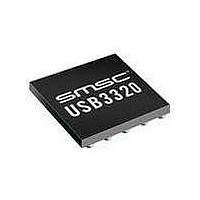
USB3300-EZK-TR SMSC, USB3300-EZK-TR Datasheet - Page 37

USB3300-EZK-TR
Manufacturer Part Number
USB3300-EZK-TR
Description
USB Interface IC USB 2.0 PHY ULPI
Manufacturer
SMSC
Type
Hi Speed USB Host Devicer
Datasheet
1.USB3300-EZK.pdf
(55 pages)
Specifications of USB3300-EZK-TR
Maximum Operating Temperature
+ 85 C
Minimum Operating Temperature
- 40 C
Mounting Style
SMD/SMT
Operating Temperature Range
- 40 C to + 85 C
Operating Supply Voltage
3.3 V
Package / Case
QFN-32
Lead Free Status / RoHS Status
Lead free / RoHS Compliant
Available stocks
Company
Part Number
Manufacturer
Quantity
Price
Company:
Part Number:
USB3300-EZK-TR
Manufacturer:
MICRON
Quantity:
3 140
Part Number:
USB3300-EZK-TR
Manufacturer:
MICROCHIP/微芯
Quantity:
20 000
Hi-Speed USB Host, Device or OTG PHY with ULPI Low Pin Interface
Datasheet
SMSC USB3300
6.1.9.4
6.1.10
In some cases, a Link may be software configured and not have control of its STP pin until after the
PHY has started. In this case, the USB3300 has an internal pull-up on the STP input pad which will
pull STP high while the Link’s STP output is tri-stated. The STP pull-up resistor is enabled on POR
and can be disabled by setting the InterfaceProtectDisable bit 7 of the Interface Control register.
The STP pull-up resistor will pull-up the Link’s STP input high until the Link configures and drives STP
high. Once the Link completes its start-up, STP can be synchronously driven low.
A Link design which drives STP high during POR can disable the pull-up resistor on STP by setting
InterfaceProtectDisable bit to 1. A motivation for this is to reduce the suspend current. In Low Power
Mode, STP is held low, which would draw current through the pull-up resistor on STP.
WARM RESET
Designers should also consider the case of a warm restart of a Link with a PHY in Low Power Mode.
Once the PHY enters Low Power Mode, DIR is asserted and the clock is stopped. The USB3300 looks
for STP to be asserted to re-start the clock and then resume normal synchronous operation.
Should the USB3300 be suspended in Low Power Mode, and the Link receives a hardware reset,
provision is made to allow the PHY to recover from Low Power Mode and start its clock. If the Link
asserts STP on reset, the PHY will exit Low Power Mode and start its clock.
If the Link does not assert STP on reset the interface protection pull-up can be used. When the Link
is reset, its STP output will tri-state and the pull-up resistor will pull STP high, signaling the PHY to
restart its clock.
Minimizing Current in Low Power Mode
In order to minimize the suspend current in Low Power Mode, the OTG comparators can be disabled
to reduce suspend current. During suspend, the VbusVld and SessEnd comparators are not needed
and can be disabled using the USB Interrupt Enable Rise and USB Interrupt Enable Fall registers. By
disabling the interrupt in BOTH the rise and fall registers, the SessEnd and VbusVld comparators are
turned off. When exiting suspend, the Link should immediately re-enable the comparators if host or
OTG functionality is needed.
In addition to disabling the OTG comparators in suspend, the Link may choose to disable the Interface
Protect Circuit. By setting the Interface Control, bit 7, InterfaceProtectDisable high, the Link can disable
the pull-up resistor on STP.
Full Speed/Low Speed Serial Modes
The USB3300 includes two serial modes to support legacy Links which use either the 3pin or 6pin
serial format. To enter either serial mode, the Link will need to write a 1 to the 6-pin FsLsSerialMode
or the 3-pin FsLsSerialMode bit in the Interface control register. The 6-pin Serial Mode is provided for
legacy link designs and is not recommended for new designs.
The serial modes are entered in the same manner as the entry into Low Power Mode. The Link writes
the Interface Control register bit for the specific serial mode. The USB3300 will assert DIR and shut
off the clock after at least five clock cycles. Then the data bus goes to the format of the serial mode
selected.
By default, the PHY will shut off the 60MHz clock to conserve power. Should the Link need the 60Mhz
clock to continue during the serial mode of operation, the ClockSuspendM bit[3] of the Interface Control
Register should be set before entering a serial mode. If set, the 60 Mhz clock will be present during
serial modes.
In serial mode, interrupts are possible from unmasked sources. The state of each interrupt source is
sampled prior to the assertion of DIR and this is compared against the asynchronous level from
interrupt source.
Exiting the serial modes is the same as exiting Low Power Mode. The Link must assert STP to signal
the PHY to exit serial mode. Then the PHY can accept a command, DIR is de-asserted and the PHY
will wait until the Link de-asserts STP to resume synchronous ULPI operation.
DATASHEET
37
Revision 1.08 (11-07-07)


