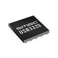
USB3300-EZK-TR SMSC, USB3300-EZK-TR Datasheet - Page 43

USB3300-EZK-TR
Manufacturer Part Number
USB3300-EZK-TR
Description
USB Interface IC USB 2.0 PHY ULPI
Manufacturer
SMSC
Type
Hi Speed USB Host Devicer
Datasheet
1.USB3300-EZK.pdf
(55 pages)
Specifications of USB3300-EZK-TR
Maximum Operating Temperature
+ 85 C
Minimum Operating Temperature
- 40 C
Mounting Style
SMD/SMT
Operating Temperature Range
- 40 C to + 85 C
Operating Supply Voltage
3.3 V
Package / Case
QFN-32
Lead Free Status / RoHS Status
Lead free / RoHS Compliant
Available stocks
Company
Part Number
Manufacturer
Quantity
Price
Company:
Part Number:
USB3300-EZK-TR
Manufacturer:
MICRON
Quantity:
3 140
Part Number:
USB3300-EZK-TR
Manufacturer:
MICROCHIP/微芯
Quantity:
20 000
Hi-Speed USB Host, Device or OTG PHY with ULPI Low Pin Interface
Datasheet
SMSC USB3300
6.5.2
6.5.2.1
6.5.2.2
6.5.2.3
be overpowered and the ID pin will be brought to ground. To save current when a Mini-A Plug is
inserted, the ID pull-up resistor can be disabled by clearing the IdPullUp bit in the OTG Control register.
To prevent the ID pin from floating to a random value, a weak pull-up resistor is provided at all times.
The circuits related to the ID comparator are shown in Figure 6.10, "USB3300 On-the-Go Module" and
their related parameters are shown in
The status of IdGnd can be read by reading the ULPI USB Interrupt Status register, bit 4. It can also
be set to generate an interrupt, in host mode, when IdGnd changes with the ULPI Interrupt Enable
registers.
VBUS Control
The USB3300 includes all of the Vbus comparators required for OTG. The VbusVld, SessVld, and
SessEnd comparators are fully integrated into the USB3300. These comparators are used to ensure
the Vbus voltage is the correct value for proper USB operation.
The VbusVld comparator is used by the Link, when configured as an A device, to ensure that the Vbus
voltage on the cable is valid. The SessVld comparator is used by the Link when configured as both
an A or B device to indicate a session is requested or valid. Finally the SessEnd comparator is used
by the B-device to indicate a USB session has ended.
Also included in the VBUS Control block are the resistors used for Vbus pulsing in SRP. The resistors
used for VBUS pulsing include a pull-down to ground and a pull-up to VDD3.3.
SessEnd Comparator
The SessEnd comparator is designed to trip when Vbus is less than 0.5 volts. When Vbus goes below
0.5 volts the session is considered to be ended and SessEnd will transition from 0 to 1. The SessEnd
compatator can be disabled by clearing this bit in both the rising and falling interrupt enable registers.
When disabled the SessEnd bit in the interrupt status register will read 0. The SessEnd comparator
trip points are detailed in
SessVld Comparator
The SessVld comparator is used when the PHY is configured as both an A and B device. When
configured as an A device, the SessVld is used to detect Session Request protocol (SRP). When
configured as a B device, SessVld is used to detect the presence of Vbus. The SessVld interrupts can
be disabled by clearing this bit in both the rising and falling interrupt enable registers. When the
interrupts are disabled, the SessVld comparator is not disabled and its state can be read in the interrupt
status register. The SessVld comparator trip point is detailed in
Note: The OTG Supplement specifies a voltage range for A-Device Session Valid and B-Device
VbusVld Comparator
The final Vbus comparator is the VbusVld comparator. This comparator is only used when configured
as an A-device. In the OTG protocol the A-device is responsible to ensure that the Vbus voltage is
within a certain range. The VbusVld comparator can be disabled by clearing both the rising and falling
edge interrupts. When disabled a read of bit 1, in the Interrupt Status Register will return a 0. The
VbusVld comparator trip points are detailed in
When the A-device is able to provide 8-100mA it must ensure Vbus doesn’t go below 4.4 volts. If the
A-device can provide 100-500mA on Vbus it must ensure that Vbus does not go below 4.75 volts.
The internal Vbus comparator is designed to ensure that Vbus remains above 4.4 volts. If the design
is required to supply over 100mA the USB3300 provides an input for a more accurate Vbus comparator
or fault (over current) detection described in
Session Valid comparator. The USB3300 PHY combines the two comparators into one and
uses the narrower threshold range.
Table
5.6.
DATASHEET
Table 5.6, "OTG Electrical
43
Section 6.5.4, "External Vbus
Table
5.6.
Table
Characteristics".
5.6.
Indicator".
Revision 1.08 (11-07-07)


