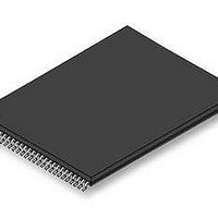
S29GL256P11TFI010 Spansion Inc., S29GL256P11TFI010 Datasheet - Page 17

S29GL256P11TFI010
Manufacturer Part Number
S29GL256P11TFI010
Description
Flash 3V 256Mb Mirrorbit highest address110ns
Manufacturer
Spansion Inc.
Specifications of S29GL256P11TFI010
Memory Type
NOR
Memory Size
256 Mbit
Access Time
110 ns
Data Bus Width
8 bit, 16 bit
Architecture
Uniform
Interface Type
Page-mode
Supply Voltage (max)
3.6 V
Supply Voltage (min)
2.7 V
Maximum Operating Current
50 mA
Mounting Style
SMD/SMT
Operating Temperature
+ 85 C
Package / Case
TSOP-56
Memory Configuration
128K X 16
Ic Interface Type
Parallel
Supply Voltage Range
2.7V To 3.6V
Memory Case Style
TSOP
No. Of Pins
56
Lead Free Status / RoHS Status
Lead free / RoHS Compliant
Lead Free Status / RoHS Status
Lead free / RoHS Compliant, Lead free / RoHS Compliant
Available stocks
Company
Part Number
Manufacturer
Quantity
Price
Company:
Part Number:
S29GL256P11TFI010
Manufacturer:
SPANSION
Quantity:
5 530
Company:
Part Number:
S29GL256P11TFI010
Manufacturer:
SPANSION
Quantity:
72
7.2
7.3
7.4
7.5
November 21, 2006 S29GL-P_00_A3
Word/Byte Configuration
VersatileIO
Read
Page Read Mode
The BYTE# pin controls whether the device data I/O pins operate in the byte or word configuration. If the
BYTE# pin is set at logic ‘1’, the device is in word con-figuration, DQ0-DQ15 are active and controlled by CE#
and OE#.
If the BYTE# pin is set at logic ‘0’, the device is in byte configuration, and only data I/O pins DQ0-DQ7 are
active and controlled by CE# and OE#. The data I/O pins DQ8-DQ14 are tri-stated, and the DQ15 pin is used
as an input for the LSB (A-1) address function.
The VersatileIO
tolerates on CE# and DQ I/Os to the same voltage level that is asserted on V
V
For example, a V
and from other 1.8 or 3 V devices on the same data bus.
All memories require access time to output array data. In a read operation, data is read from one memory
location at a time. Addresses are presented to the device in random order, and the propagation delay through
the device causes the data on its outputs to arrive with the address on its inputs.
The device defaults to reading array data after device power-up or hardware re-set. To read data from the
memory array, the system must first assert a valid address on Amax-A0, while driving OE# and CE# to V
WE# must remain at V
DQ0 after ad-dress access time (t
The OE# signal must be driven to V
elapsed from the falling edge of OE#.
The device is capable of fast page mode read and is compatible with the page mode Mask ROM read
operation. This mode provides faster read access speed for random locations within a page. The page size of
the device is 8 words/16 bytes. The appropriate page is selected by the higher address bits A(max)-A3.
Address bits A2-A0 in word mode (A2-A-1 in byte mode) determine the specific word within a page. The
microprocessor supplies the specific word location.
The random or initial page access is equal to t
locations specified by the microprocessor falls within that page) is equivalent to t
asserted and reasserted for a subsequent access, the access time is t
are obtained by keeping the “read-page addresses” constant and changing the “intra-read page” addresses.
IO
D a t a
options on this device.
TM
(V
S h e e t
TM
IO
IO
(V
) Control
of 1.65-3.6 volts allows for I/O at the 1.8 or 3 volt levels, driving and receiving signals to
IO
) control allows the host system to set the voltage levels that the device generates and
IH
. All addresses are latched on the falling edge of CE#. Data will appear on DQ15-
( A d v a n c e
S29GL-P MirrorBit
ACC
IL
), which is equal to the delay from stable addresses to valid output data.
. Data is output on DQ15-DQ0 pins after the access time (t
I n f o r m a t i o n )
ACC
TM
Flash Family
or t
CE
and subsequent page read accesses (as long as the
ACC
or t
IO
CE
. See Ordering Information for
PACC
. Fast page mode accesses
. When CE# is de-
OE
) has
IL
15
.


