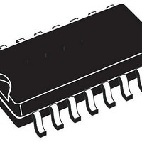
VIPER26HD STMicroelectronics, VIPER26HD Datasheet

VIPER26HD
Specifications of VIPER26HD
Available stocks
Related parts for VIPER26HD
VIPER26HD Summary of contents
Page 1
... LED drivers ■ SMPS for set-top boxes, DVD players and recorders Table 1. Device summary Order codes VIPER26LN VIPER26HN VIPER26HD VIPER26HDTR VIPER26LD VIPER26LDTR September 2010 Fixed frequency VIPer SO16 narrow SO-16 Description The device is an off-line converter with an 800 V AC avalanche ruggedness power section, a PWM ...
Page 2
Contents Contents 1 Block diagram . . . . . . . . . . . . . . . . . . . . . . . . . . . . . . . . . . . ...
Page 3
VIPER26 1 Block diagram Figure 2. Block diagram 2 Typical power Table 2. Typical power Part number VIPER26 1. Typical continuous power in non ventilated enclosed adapter measured Maximum practical continuous power in an open frame design ...
Page 4
Pin settings 3 Pin settings Figure 3. Connection diagram (top view) Note: The copper area for heat dissipation has to be designed under the DRAIN pins. Table 3. Pin description Pin n. Name DIP-7 SO16 1 1-2 GND - 4 ...
Page 5
VIPER26 4 Electrical data 4.1 Maximum ratings Table 4. Absolute maximum ratings Pin Symbol (DIP- DRAIN DRAIN V 5 COMP LIM ...
Page 6
Electrical data 4.3 Electrical characteristics (T = -25 to 125 ° Table 6. Power section Symbol Parameter V Break-down voltage BVDSS I OFF state drain current OFF Drain-source on state R DS(on) resistance Effective (energy related) C OSS ...
Page 7
VIPER26 Table 8. Controller section Symbol Parameter Error amplifier V FB reference voltage REF_FB I Current pull up FB_PULL UP G Trans conductance M Current setting (LIM) pin V Low level clamp voltage LIM_LOW Compensation (COMP) pin V Upper saturation ...
Page 8
Typical electrical characteristics 5 Typical electrical characteristics Figure 4. IDlim Figure DRAIN_START Figure 8/25 Figure 5. Figure 7. J Figure 9. Doc ID 17736 Rev 2 VIPER26 ...
Page 9
VIPER26 Figure 10 COMP J Figure 12. Operating supply current (switching Figure 14. Power MOSFET on-resistance vs T Figure 11. Operating supply current Figure 13. IDlim Figure 15. Power MOSFET break down ...
Page 10
Typical circuits Figure 16. Thermal shutdown DDon V DDCSon V DDoff I DRAIN HYST Normal operation 6 Typical circuits Figure 17. Buck converter (V 10/25 Shut down after over ...
Page 11
VIPER26 Figure 18. Fly-back converter (isolated) Figure 19. Flyback converter (primary regulation) Doc ID 17736 Rev 2 Typical circuits 11/25 ...
Page 12
Typical circuits Figure 20. Flyback converter (non isolated, V Figure 21. Flyback converter (non isolated, V 12/ OUT DDCSon V [ OUT DDCSon Doc ID 17736 Rev 2 VIPER26 ) ) ...
Page 13
VIPER26 7 Power section The power section is implemented with an n-channel power MOSFET with a breakdown voltage of 800 V min. and a typical R a virtually lossless current sensing and the thermal sensor. The gate driver of the ...
Page 14
Oscillator 9 Oscillator The switching frequency is internally fixed at 60 kHz (VIPER26LN or LD) or 115 kHz (VIPER26HN or HD). In both cases the switching frequency is modulated by approximately ±4 kHz (60 kHz version) or ±8 kHz (115 ...
Page 15
VIPER26 12 FB pin and COMP pin The device can be used both in non-isolated and in isolated topology. In case of non- isolated topology, the feedback signal from the output voltage is applied directly to the FB pin as ...
Page 16
Burst mode Figure 24. COMP pin voltage versus I 13 Burst mode When the voltage V OFF state and the consumption is reduced to I page 6. As reaction at the energy delivery stop, the exceeds the ...
Page 17
VIPER26 14 Automatic auto restart after overload or short-circuit The overload protection is implemented in automatic way using the integrated up-down counter. Every cycle incremented or decremented depending if the current logic detects the limit condition or not. ...
Page 18
Open loop failure protection 15 Open loop failure protection In case the power supply is built in fly-back topology and the VIPer26 is supplied by an auxiliary winding, as shown in converter is protected against feedback loop failure or accidental ...
Page 19
VIPER26 Figure 28. FB pin connection for isolated fly-back Doc ID 17736 Rev 2 Open loop failure protection 19/25 ...
Page 20
Package mechanical data 16 Package mechanical data In order to meet environmental requirements, ST offers these devices in different grades of ® ECOPACK packages, depending on their level of environmental compliance. ECOPACK specifications, grade definitions and product status are available ...
Page 21
VIPER26 Figure 29. DIP-7 package dimensions Doc ID 17736 Rev 2 Package mechanical data 21/25 ...
Page 22
Package mechanical data Table 10. SO16N mechanical data Dim ccc 22/25 mm Min Typ 0.1 1.25 0.31 0.17 9.8 9.9 5.8 6 3.8 3.9 1.27 0.25 0.4 0 ...
Page 23
VIPER26 Figure 30. SO16N package dimensions Doc ID 17736 Rev 2 Package mechanical data 23/25 ...
Page 24
Revision history 17 Revision history Table 11. Document revision history Date 26-Aug-2010 01-Sep-2010 24/25 Revision 1 Initial release. Figure 30 on page 2 Updated Doc ID 17736 Rev 2 VIPER26 Changes 23. ...
Page 25
... VIPER26 Information in this document is provided solely in connection with ST products. STMicroelectronics NV and its subsidiaries (“ST”) reserve the right to make changes, corrections, modifications or improvements, to this document, and the products and services described herein at any time, without notice. All ST products are sold pursuant to ST’s terms and conditions of sale. ...


