A3PN030-ZQNG68 Actel, A3PN030-ZQNG68 Datasheet
A3PN030-ZQNG68
Specifications of A3PN030-ZQNG68
Available stocks


Related parts for A3PN030-ZQNG68


A3PN030-ZQNG68 Summary of contents
Page 1
... Notes: 1. A3PN030 is available in the Z feature grade only. 2. A3PN030 and smaller devices do not support this feature. 3. For higher densities and support of additional features, refer to the † A3PN030 and smaller devices do not support this feature. April 2010 © 2010 Actel Corporation Advanced I/Os • ...
Page 2
... VQ100 – Notes: 1. A3PN030 is available in the Z feature grade only. 2. When considering migrating your design to a lower- or higher-density device, refer to the to ensure compliance with design and board migration requirements. 3. "G" indicates RoHS-compliant packages. Refer to in the part number. For nano devices, the VQ100 package is offered in both leaded and RoHS-compliant versions. All other packages are RoHS-compliant only. Table 2 • ...
Page 3
... A3PN060, A3PN125, and A3PN250, the Z feature grade does not support the enhanced nano features of Schmitt trigger input, cold-sparing, and hot-swap I/O capability. The A3PN030 Z feature grade does not support Schmitt trigger input. For the VQ100, CS81, UC81, QN68, and QN48 packages, the Z feature grade and the N part number are not marked on the device ...
Page 4
... ProASIC3 nano-Z Devices QN48 C, I QN68 – VQ100 – Notes: 1. A3PN030 is available in the Z feature grade only Commercial temperature range: –20°C to 70°C ambient temperature Industrial temperature range: –40°C to 85°C ambient temperature Speed Grade and Temperature Grade Matrix Temperature Grade ...
Page 5
... Global Resource Characteristics . . . . . . . . . . . . . . . . . . . . . . . . . . . . . . . . . . . . . . . . . . . . . . . . . . . . . . . . . . . . . . . 2-53 Clock Conditioning Circuits . . . . . . . . . . . . . . . . . . . . . . . . . . . . . . . . . . . . . . . . . . . . . . . . . . . . . . . . . . . . . . . . . . . 2-57 Embedded SRAM and FIFO Characteristics . . . . . . . . . . . . . . . . . . . . . . . . . . . . . . . . . . . . . . . . . . . . . . . . . . . . . . 2-59 Embedded FlashROM Characteristics . . . . . . . . . . . . . . . . . . . . . . . . . . . . . . . . . . . . . . . . . . . . . . . . . . . . . . . . . . 2-69 JTAG 1532 Characteristics . . . . . . . . . . . . . . . . . . . . . . . . . . . . . . . . . . . . . . . . . . . . . . . . . . . . . . . . . . . . . . . . . . . 2-70 Actel Safety Critical, Life Support, and High-Reliability Applications Policy . . . . . . . . . . . . . . . . . . . . . . . . . . . . . . 2-70 Package Pin Assignments 48-Pin QFN . . . . . . . . . . . . . . . . . . . . . . . . . . . . . . . . . . . . . . . . . . . . . . . . . . . . . . . . . . . . . . . . . . . . . . . . . . . . . . . . 3-1 68-Pin QFN . . . . . . . . . . . . . . . . . . . . . . . . . . . . . . . . . . . . . . . . . . . . . . . . . . . . . . . . . . . . . . . . . . . . . . . . . . . . . . . . 3-4 100-Pin VQFP . . . . . . . . . . . . . . . . . . . . . . . . . . . . . . . . . . . . . . . . . . . . . . . . . . . . . . . . . . . . . . . . . . . . . . . . . . . . . . 3-8 Datasheet Information List of Changes ...
Page 6
...
Page 7
... ProASIC3 nano devices offer 1 kbit of on-chip, reprogrammable, nonvolatile FlashROM storage as well as clock conditioning circuitry based on an integrated phase-locked loop (PLL). A3PN030 and smaller devices do not have PLL or RAM support. ProASIC3 nano devices have up to 250,000 system gates, supported with kbits of true dual-port SRAM and user I/Os ...
Page 8
... Live at Power-Up Actel flash-based ProASIC3 nano devices support Level 0 of the LAPU classification standard. This feature helps in system component initialization, execution of critical tasks before the processor wakes up, setup and configuration of memory blocks, clock generation, and bus activity management. The ...
Page 9
... Advanced I/O structure User Nonvolatile FlashROM Note: *Bank 0 for the A3PN030 device Figure 1-1 • ProASIC3 Device Architecture Overview with Two I/O Banks and No RAM (A3PN010 and A3PN030) User Nonvolatile FlashROM Figure 1-2 • ProASIC3 nano Architecture Overview with Three I/O Banks and No RAM (A3PN015 and ...
Page 10
... The versatility of the ProASIC3 nano core tile as either a three-input lookup table (LUT) equivalent D-flip-flop/latch with enable allows for efficient use of the FPGA fabric. The VersaTile capability is unique to the Actel ProASIC3 family of third-generation architecture flash FPGAs. VersaTiles are connected with any of the four levels of routing hierarchy. Flash switches are distributed throughout the device to provide nonvolatile, reconfigurable interconnect programming ...
Page 11
... The FlashROM is written using the standard ProASIC3 nano IEEE 1532 JTAG programming interface. The core can be individually programmed (erased and written), and on-chip AES decryption can be used selectively to securely load data over public networks (except in the A3PN030 and smaller devices security keys stored in the FlashROM for a user design. ...
Page 12
... A3PN060, A3PN125, and A3PN250 contain six CCCs. One CCC (center west side) has a PLL. The A3PN030 and smaller devices use different CCCs in their architecture. These CCC-GLs contain a global MUX but do not have any PLLs or programmable delays ...
Page 13
... Wide Range I/O Support Actel nano devices support JEDEC-defined wide range I/O operation. ProASIC3 nano supports the JESD8-B specification, covering both 3 V and 3.3 V supplies, for an effective operating range of 2 3.6 V. ...
Page 14
...
Page 15
ProASIC3 nano DC and Switching Characteristics General Specifications The Z feature grade does not support the enhanced nano features of Schmitt trigger input, cold-sparing, and hot-swap I/O capability. Refer to the more information. DC and switching characteristics for ...
Page 16
... All parameters representing voltages are measured with respect to GND unless otherwise specified ensure targeted reliability standards are met across ambient and junction operating temperatures, Actel recommends that the user follow best design practices using Actel’s timing and power simulation tools. ...
Page 17
... JTAG supply, PLL power supplies, and charge pump VPUMP supply have no influence on I/O behavior. PLL Behavior at Brownout Condition Actel recommends using monotonic power supplies or voltage regulators to ensure proper power-up behavior. Power ramp-up should be monotonic at least until VCC and VCCPLLX exceed brownout activation levels. The VCC activation level is specified as 1.1 V worst-case (see for more details). When PLL power supply voltage and/or VCC levels drop below the VCC brownout levels (0.75 V ± ...
Page 18
ProASIC3 nano DC and Switching Characteristics Internal Power-Up Activation Sequence 1. Core 2. Input buffers 3. Output buffers, after 200 ns delay from input buffer activation VCC = VCCI + VT where VT can be from 0. 0.9 ...
Page 19
... Thermal Characteristics Introduction The temperature variable in the Actel Designer software refers to the junction temperature, not the ambient temperature. This is an important distinction because dynamic and static power consumption cause the chip junction to be higher than the ambient temperature can be used to calculate junction temperature. ...
Page 20
ProASIC3 nano DC and Switching Characteristics Calculating Power Dissipation Quiescent Supply Current Table 2-7 • Quiescent Supply Current Characteristics Typical (25°C) Max. (Commercial) Max. (Industrial) Note: I includes VCC, VPUMP, and VCCI, currents. DD Power per I/O Pin Table 2-8 ...
Page 21
Table 2-9 • Summary of I/O Output Buffer Power (per pin) – Default I/O Software Settings C LOAD Single-Ended 3.3 V LVTTL / 3.3 V LVCMOS 4 3.3 V LVCMOS wide range 2.5 V LVCMOS 1.8 V LVCMOS 1.5 V ...
Page 22
... DC4 P Bank quiescent power (VCCI-dependent) DC5 Notes: 1. Minimum contribution of the PLL when running at lowest frequency. 2. For a different output load, drive strength, or slew rate, Actel recommends using the Actel Power spreadsheet calculator or SmartPower tool in Libero IDE Device Specific Dynamic Contributions Definition 11.03 1.58 ® ...
Page 23
... Power Calculation Methodology This section describes a simplified method to estimate power consumption of an application. For more accurate and detailed power estimations, use the SmartPower tool in Actel Libero IDE software. The power calculation methodology described below uses the following variables: • The number of PLLs as well as the number and the frequency of each output clock generated • ...
Page 24
ProASIC3 nano DC and Switching Characteristics Combinatorial Cells Contribution— C-CELL C-CELL N is the number of VersaTiles used as combinatorial modules in the design. C-CELL α is the toggle rate of VersaTile outputs—guidelines are provided in 1 ...
Page 25
Guidelines Toggle Rate Definition A toggle rate defines the frequency of a net or logic element relative to a clock percentage. If the toggle rate of a net is 100%, this means that this net switches at ...
Page 26
ProASIC3 nano DC and Switching Characteristics User I/O Characteristics Timing Model I/O Module (Registered 1. Input LVCMOS 2 0.24 ns ICLKQ t = 0.26 ns ISUD Input LVTTL Clock t = ...
Page 27
PY PAD t = MAX MAX(t DIN V trip PAD 50% Y GND t PY (R) DIN GND Figure 2-3 • Input Buffer Timing Model and Delays (example) t DIN CLK I/O Interface ...
Page 28
ProASIC3 nano DC and Switching Characteristics D CLK D From Array I/O Interface D DOUT PAD Figure 2-4 • Output Buffer Model and Delays (example DOUT Q DOUT t = MAX MAX(t DOUT ...
Page 29
EOUT D Q CLK CLK D I/O Interface D 50 EOUT (R) 50% EOUT t ZL PAD Vtrip VOL D 50 EOUT (R) VCC 50% EOUT t ZLS PAD Vtrip VOL Figure ...
Page 30
ProASIC3 nano DC and Switching Characteristics Overview of I/O Performance Summary of I/O DC Input and Output Levels – Default I/O Software Settings Table 2-14 • Summary of Maximum and Minimum DC Input and Output Levels Applicable to Commercial and ...
Page 31
Summary of I/O Timing Characteristics – Default I/O Software Settings Table 2-16 • Summary of AC Measuring Points Standard 3.3 V LVTTL / 3.3 V LVCMOS 3.3 V LVCMOS Wide Range 2.5 V LVCMOS 1.8 V LVCMOS 1.5 V LVCMOS ...
Page 32
ProASIC3 nano DC and Switching Characteristics Table 2-18 • Summary of I/O Timing Characteristics—Software Default Settings (at 35 pF) STD Speed Grade, Commercial-Case Conditions: T For A3PN060, A3PN125, and A3PN250 I/O Standard 3.3 V LVTTL / 3.3 ...
Page 33
... These maximum values are provided for informational reasons only. Minimum output buffer resistance values depend drive strength selection, temperature, and process. For board design CCI considerations and detailed output buffer resistances, use the corresponding IBIS models located on the Actel website at http://www.actel.com/download/ibis/default.aspx (VOLspec) / IOLspec (PULL-DOWN-MAX (VCCImax – ...
Page 34
ProASIC3 nano DC and Switching Characteristics Table 2-23 • I/O Short Currents I 3.3 V LVTTL / 3.3 V LVCMOS 3.3 V LVCMOS Wide Range 2.5 V LVCMOS 1.8 V LVCMOS 1.5 V LVCMOS Note 100°C J The ...
Page 35
... The longer the rise/fall times, the more susceptible the input signal is to the board noise. Actel recommends signal integrity evaluation/characterization of the system to ensure that there is no excessive noise coupling into input signals. ...
Page 36
ProASIC3 nano DC and Switching Characteristics Single-Ended I/O Characteristics 3.3 V LVTTL / 3.3 V LVCMOS Low-Voltage Transistor–Transistor Logic (LVTTL general-purpose standard (EIA/JESD) for 3.3 V applications. It uses an LVTTL input buffer and push-pull output buffer. Table ...
Page 37
Timing Characteristics Table 2-29 • 3.3 V LVTTL / 3.3 V LVCMOS Low Slew Commercial-Case Conditions: T Software Default Load for A3PN060, A3PN125, A3PN250 Drive Speed Strength Grade t t DOUT Std. 0.60 9.70 ...
Page 38
ProASIC3 nano DC and Switching Characteristics Table 2-31 • 3.3 V LVTTL / 3.3 V LVCMOS Low Slew Commercial-Case Conditions: T Software Default Load for A3PN020, A3PN015, A3PN010 Drive Speed Strength Grade t DOUT 2 mA Std. ...
Page 39
V LVCMOS Wide Range Table 2-33 • Minimum and Maximum DC Input and Output Levels for 3.3 V LVCMOS Wide Range 3.3 V LVCMOS Wide Range Equivalent Software Default Drive Strength Min. 3 Drive Strength Option V 100 µA ...
Page 40
ProASIC3 nano DC and Switching Characteristics Timing Characteristics Table 2-34 • 3.3 V LVCMOS Wide Range Low Slew Commercial-Case Conditions: T Software Default Load for A3PN060, A3PN125, A3PN250 Equivalent Software Default Drive Drive Strength Speed 1 Strength ...
Page 41
Table 2-35 • 3.3 V LVCMOS Wide Range High Slew Commercial-Case Conditions: T Software Default Load for A3PN060, A3PN125, A3PN250 Equivalent Software Default Drive Drive Strength Speed 1 Strength Option Grade t DOUT 100 µ ...
Page 42
ProASIC3 nano DC and Switching Characteristics Table 2-36 • 3.3 V LVCMOS Wide Range Low Slew Commercial-Case Conditions: T Software Default Load for A3PN020, A3PN015, A3PN010 Equivalent Software Default Drive Drive Strength Speed 1 Strength Option Grade ...
Page 43
Table 2-37 • 3.3 V LVCMOS Wide Range High Slew Commercial-Case Conditions: T Software Default Load for A3PN020, A3PN015, A3PN010 Equivalent Software Default Drive Drive Strength Speed 1 Strength Option Grade t DOUT 100 µ ...
Page 44
ProASIC3 nano DC and Switching Characteristics 2.5 V LVCMOS Low-Voltage CMOS for 2 extension of the LVCMOS standard (JESD8-5) used for general- purpose 2.5 V applications. Table 2-38 • Minimum and Maximum DC Input and Output Levels ...
Page 45
Timing Characteristics Table 2-40 • 2.5 V LVCMOS Low Slew Commercial-Case Conditions: T Software Default Load for A3PN060, A3PN125, A3PN250 Drive Speed Strength Grade t t DOUT Std. 0.60 11.29 –1 0.51 9.61 –2 ...
Page 46
ProASIC3 nano DC and Switching Characteristics Table 2-42 • 2.5 V LVCMOS Low Slew Commercial-Case Conditions: T Software Default Load for A3PN020, A3PN015, A3PN010 Drive Speed Strength Grade t DOUT 2 mA Std. 0.60 –1 0.51 –2 ...
Page 47
V LVCMOS Low-voltage CMOS for 1 extension of the LVCMOS standard (JESD8-5) used for general- purpose 1.8 V applications. It uses a 1.8 V input buffer and a push-pull output buffer. Table 2-44 • Minimum and ...
Page 48
ProASIC3 nano DC and Switching Characteristics Timing Characteristics Table 2-46 • 1.8 V LVCMOS Low Slew Commercial-Case Conditions: T Software Default Load for A3PN060, A3PN125, A3PN250 Drive Speed Strength Grade t DOUT 2 mA Std. 0.60 –1 ...
Page 49
Table 2-48 • 1.8 V LVCMOS Low Slew Commercial-Case Conditions: T Software Default Load for A3PN020, A3PN015, A3PN010 Drive Speed Strength Grade t t DOUT Std. 0.60 8.52 –1 0.51 7.25 –2 0.45 6.36 ...
Page 50
ProASIC3 nano DC and Switching Characteristics 1.5 V LVCMOS (JESD8-11) Low-Voltage CMOS for 1 extension of the LVCMOS standard (JESD8-5) used for general- purpose 1.5 V applications. It uses a 1.5 V input buffer and a push-pull ...
Page 51
Timing Characteristics Table 2-52 • 1.5 V LVCMOS Low Slew Commercial-Case Conditions: T Software Default Load for A3PN060, A3PN125, A3PN250 Drive Speed Strength Grade t t DOUT Std. 0.60 12.58 –1 0.51 10.70 –2 ...
Page 52
ProASIC3 nano DC and Switching Characteristics I/O Register Specifications Fully Registered I/O Buffers with Synchronous Enable and Asynchronous Preset Preset Data C Enable B CLK A Data Input I/O Register with: Active High Enable Active High Preset Positive-Edge Triggered Figure ...
Page 53
Table 2-56 • Parameter Definition and Measuring Nodes Parameter Name t Clock-to-Q of the Output Data Register OCLKQ t Data Setup Time for the Output Data Register OSUD t Data Hold Time for the Output Data Register OHD t Enable ...
Page 54
ProASIC3 nano DC and Switching Characteristics Fully Registered I/O Buffers with Synchronous Enable and Asynchronous Clear Data CC Enable BB CLK AA CLR DD Data Input I/O Register with Active High Enable Active High Clear Positive-Edge Triggered Figure 2-11 • ...
Page 55
Table 2-57 • Parameter Definition and Measuring Nodes Parameter Name t Clock-to-Q of the Output Data Register OCLKQ t Data Setup Time for the Output Data Register OSUD t Data Hold Time for the Output Data Register OHD t Enable ...
Page 56
ProASIC3 nano DC and Switching Characteristics Input Register 50% CLK 1 50% Data Enable 50% t IHE t ISUE Preset Clear Out_1 Figure 2-12 • Input Register Timing Diagram Timing Characteristics Table 2-58 • Input Data Register Propagation Delays Commercial-Case ...
Page 57
Output Register 50% 50% CLK t 50% 1 Data_out Enable 50% t OHE t Preset OSUE Clear DOUT Figure 2-13 • Output Register Timing Diagram Timing Characteristics Table 2-59 • Output Data Register Propagation Delays Commercial-Case Conditions: T Parameter t ...
Page 58
ProASIC3 nano DC and Switching Characteristics Output Enable Register 50% CLK 50% 1 D_Enable 50% Enable t t OESUE OEHE Preset Clear EOUT Figure 2-14 • Output Enable Register Timing Diagram Timing Characteristics Table 2-60 • Output Enable Register Propagation ...
Page 59
DDR Module Specifications Input DDR Module INBUF A Data B CLK CLKBUF C CLR INBUF Figure 2-15 • Input DDR Timing Model Table 2-61 • Parameter Definitions Parameter Name Parameter Definition t Clock-to-Out Out_QR DDRICLKQ1 t Clock-to-Out Out_QF DDRICLKQ2 t ...
Page 60
ProASIC3 nano DC and Switching Characteristics CLK Data 1 2 CLR t DDRIREMCLR t DDRICLR2Q1 Out_QF t DDRICLR2Q2 Out_QR Figure 2-16 • Input DDR Timing Diagram Timing Characteristics Table 2-62 • Input DDR Propagation Delays Commercial-Case Conditions: T Parameter t ...
Page 61
Output DDR Module A Data_F (from core) B CLK CLKBUF C D Data_R (from core) B CLR INBUF C Figure 2-17 • Output DDR Timing Model Table 2-63 • Parameter Definitions Parameter Name Parameter Definition t Clock-to-Out DDROCLKQ t Asynchronous ...
Page 62
ProASIC3 nano DC and Switching Characteristics CLK Data_F DDROREMCLR Data_R CLR DDROREMCLR t DDROCLR2Q Out Figure 2-18 • Output DDR Timing Diagram Timing Characteristics Table 2-64 • Output DDR Propagation Delays Commercial-Case Conditions: T ...
Page 63
VersaTile Characteristics VersaTile Specifications as a Combinatorial Module The ProASIC3 library offers all combinations of LUT-3 combinatorial functions. In this section, timing characteristics are presented for a sample of the library. For more details, refer to the and ProASIC3/E Macro ...
Page 64
ProASIC3 nano DC and Switching Characteristics OUT GND VCC OUT Figure 2-20 • Timing Model and Waveforms NAND2 or Any Combinatorial Logic MAX(t PD PD(RR) where edges are applicable ...
Page 65
Timing Characteristics Table 2-65 • Combinatorial Cell Propagation Delays Commercial-Case Conditions: T Combinatorial Cell Equation INV AND2 · B NAND2 Y = !(A · B) OR2 NOR2 Y = ...
Page 66
ProASIC3 nano DC and Switching Characteristics 50% CLK 50% Data EN 50 PRE SUE CLR Out Figure 2-22 • Timing Model and Waveforms Timing Characteristics Table 2-66 • Register Delays Commercial-Case Conditions: T Parameter t Clock-to-Q of ...
Page 67
Global Resource Characteristics A3PN250 Clock Tree Topology Clock delays are device-specific. global tree presented in Figure 2- used to drive all D-flip-flops in the device. CCC Figure 2-23 • Example of Global Tree Use in an A3PN250 Device ...
Page 68
ProASIC3 nano DC and Switching Characteristics Global Tree Timing Characteristics Global clock delays include the central rib delay, the spine delay, and the row delay. Delays do not include I/O input buffer clock delays, as these are I/O standard–dependent, and ...
Page 69
Table 2-69 • A3PN020 Global Resource Commercial-Case Conditions: T Parameter Description t Input LOW Delay for Global Clock RCKL t Input HIGH Delay for Global Clock RCKH t Minimum Pulse Width HIGH for Global Clock RCKMPWH t Minimum Pulse Width ...
Page 70
ProASIC3 nano DC and Switching Characteristics Table 2-71 • A3PN125 Global Resource Commercial-Case Conditions: T Parameter Description t Input LOW Delay for Global Clock RCKL t Input HIGH Delay for Global Clock RCKH t Minimum Pulse Width HIGH for Global ...
Page 71
Clock Conditioning Circuits CCC Electrical Specifications Timing Characteristics Table 2-73 • ProASIC3 nano CCC/PLL Specification Parameter Clock Conditioning Circuitry Input Frequency f Clock Conditioning Circuitry Output Frequency f Delay Increments in Programmable Delay Blocks Number of Programmable Values in Each ...
Page 72
ProASIC3 nano DC and Switching Characteristics Output Signal Note: Peak-to-peak jitter measurements are defined by T Figure 2-24 • Peak-to-Peak Jitter Definition period_max period_min = T – T peak-to-peak period_max period_min R e visio n 8 ...
Page 73
Embedded SRAM and FIFO Characteristics SRAM ADDRA11 ADDRA10 ADDRA0 DINA8 DINA7 DINA0 WIDTHA1 WIDTHA0 PIPEA WMODEA BLKA WENA CLKA ADDRB11 ADDRB10 ADDRB0 DINB8 DINB7 DINB0 WIDTHB1 WIDTHB0 PIPEB WMODEB BLKB WENB CLKB Figure 2-25 • RAM Models RAM4K9 RAM512X18 RADDR8 ...
Page 74
ProASIC3 nano DC and Switching Characteristics Timing Waveforms CLK ADD t BKS BLK_B t ENS WEN_B Figure 2-26 • RAM Read for Pass-Through Output CLK ADD t BKS BLK_B t ENS ...
Page 75
CYC t CKH CLK ADD 0 t BKS BLK_B t ENS WEN_B Figure 2-28 • RAM Write, Output Retained (WMODE = 0) t CKH CLK ...
Page 76
ProASIC3 nano DC and Switching Characteristics CLK RESET_B Figure 2-30 • RAM Reset CYC t t CKH CKL visio RSTBQ ...
Page 77
Timing Characteristics Table 2-74 • RAM4K9 Commercial-Case Conditions: T Parameter t Address Setup time AS t Address Hold time AH t REN_B, WEN_B Setup time ENS t REN_B, WEN_B Hold time ENH t BLK_B Setup time BKS t BLK_B Hold ...
Page 78
ProASIC3 nano DC and Switching Characteristics Table 2-75 • RAM512X18 Commercial-Case Conditions: T Parameter t Address setup time AS t Address hold time AH t REN_B, WEN_B setup time ENS t REN_B, WEN_B hold time ENH t Input data (DI) ...
Page 79
FIFO RW2 RW1 RW0 WW2 WW1 WW0 ESTOP FSTOP AEVAL11 AEVAL10 AEVAL0 AFVAL11 AFVAL10 AFVAL0 REN RBLK RCLK WD17 WD16 WD0 WEN WBLK WCLK RPIPE Figure 2-31 • FIFO Model ProASIC3 nano Flash FPGAs FIFO4K18 RD17 RD16 RD0 FULL AFULL ...
Page 80
ProASIC3 nano DC and Switching Characteristics Timing Waveforms RCLK/ WCLK RESET_B EMPTY AEMPTY FULL AFULL WA/RA (Address Counter) Figure 2-32 • FIFO Reset RCLK EMPTY AEMPTY WA/RA NO MATCH (Address Counter) Figure 2-33 • FIFO EMPTY Flag and AEMPTY Flag ...
Page 81
WCLK FULL AFULL WA/RA NO MATCH (Address Counter) Figure 2-34 • FIFO FULL Flag and AFULL Flag Assertion WCLK MATCH WA/RA NO MATCH (Address Counter) (EMPTY) 1st Rising Edge After 1st Write RCLK EMPTY AEMPTY Figure 2-35 • FIFO EMPTY ...
Page 82
ProASIC3 nano DC and Switching Characteristics Timing Characteristics Table 2-76 • FIFO Worst Commercial-Case Conditions: T Parameter t REN_B, WEN_B Setup Time ENS t REN_B, WEN_B Hold Time ENH t BLK_B Setup Time BKS t BLK_B Hold Time BKH t ...
Page 83
Embedded FlashROM Characteristics t SU CLK t HOLD Address A 0 Data Figure 2-37 • Timing Diagram Timing Characteristics Table 2-77 • Embedded FlashROM Access Time Commercial-Case Conditions: T Parameter Description t Address Setup Time SU t Address Hold Time ...
Page 84
... Actel may amend or enhance products during the product introduction and qualification process, resulting in changes in device functionality or performance the responsibility of each customer to ensure the fitness of any Actel product (but especially a new product) for a particular purpose, including appropriateness for safety-critical, life-support, and other high-reliability applications. ...
Page 85
... Package Pin Assignments 48-Pin QFN Notes: 1. This is the bottom view of the package. 2. The die attach paddle of the package is tied to ground (GND). Note For Package Manufacturing and Environmental information, visit the Resource Center at http://www.actel.com/products/solutions/package/docs.aspx. ProASIC3 nano Flash FPGAs Pin ...
Page 86
Package Pin Assignments 48-Pin QFN A3PN010 Pin Number Function 1 GEC0/IO37RSB1 2 IO36RSB1 3 GEA0/IO34RSB1 4 IO22RSB1 5 GND 6 VCCIB1 7 IO24RSB1 8 IO33RSB1 9 IO26RSB1 10 IO32RSB1 11 IO27RSB1 12 IO29RSB1 13 IO30RSB1 14 IO31RSB1 15 IO28RSB1 16 ...
Page 87
... VCC 19 VCCIB1 20 IO46RSB1 21 IO42RSB1 22 TCK 23 TDI 24 TMS 25 VPUMP 26 TDO 27 TRST 28 VJTAG 29 IO38RSB0 30 GDB0/IO34RSB0 31 GDA0/IO33RSB0 32 GDC0/IO32RSB0 33 VCCIB0 34 GND 35 VCC 48-Pin QFN A3PN030Z Pin Number Function 36 IO25RSB0 37 IO24RSB0 38 IO22RSB0 39 IO20RSB0 40 IO18RSB0 41 IO16RSB0 42 IO14RSB0 43 IO10RSB0 44 IO08RSB0 45 IO06RSB0 46 IO04RSB0 47 IO02RSB0 48 IO00RSB0 ProASIC3 nano Flash FPGAs 3 -3 ...
Page 88
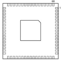
... Package Pin Assignments 68-Pin QFN Notes: 1. This is the bottom view of the package. 2. The die attach paddle of the package is tied to ground (GND). Note For Package Manufacturing and Environmental information, visit the Resource Center at http://www.actel.com/products/solutions/package/docs.aspx Pin A1 Mark ...
Page 89
QFN Pin Number A3PN015 Function 1 IO60RSB2 2 IO54RSB2 3 IO52RSB2 4 IO50RSB2 5 IO49RSB2 6 GEC0/IO48RSB2 7 GEA0/IO47RSB2 8 VCC 9 GND 10 VCCIB2 11 IO46RSB2 12 IO45RSB2 13 IO44RSB2 14 IO43RSB2 15 IO42RSB2 16 IO41RSB2 17 IO40RSB2 ...
Page 90
Package Pin Assignments 68-Pin QFN A3PN020 Pin Number Function 1 IO60RSB2 2 IO54RSB2 3 IO52RSB2 4 IO50RSB2 5 IO49RSB2 6 GEC0/IO48RSB2 7 GEA0/IO47RSB2 8 VCC 9 GND 10 VCCIB2 11 IO46RSB2 12 IO45RSB2 13 IO44RSB2 14 IO43RSB2 15 IO42RSB2 16 ...
Page 91
... IO58RSB1 20 IO56RSB1 21 IO54RSB1 22 IO52RSB1 23 IO51RSB1 24 VCC 25 GND 26 VCCIB1 27 IO50RSB1 28 IO48RSB1 29 IO46RSB1 30 IO44RSB1 31 IO42RSB1 32 TCK 33 TDI 34 TMS 35 VPUMP 36 TDO 68-Pin QFN Pin Number A3PN030Z Function 37 TRST 38 VJTAG 39 IO40RSB0 40 IO37RSB0 41 GDB0/IO34RSB0 42 GDA0/IO33RSB0 43 GDC0/IO32RSB0 44 VCCIB0 45 GND 46 VCC 47 IO31RSB0 48 IO29RSB0 49 IO28RSB0 50 IO27RSB0 51 IO25RSB0 52 IO24RSB0 53 IO22RSB0 54 ...
Page 92
... Package Pin Assignments 100-Pin VQFP 100 1 Note: This is the top view of the package. Note For Package Manufacturing and Environmental information, visit the Resource Center at http://www.actel.com/products/solutions/package/docs.aspx ...
Page 93
... TRST 56 VJTAG 57 IO41RSB0 58 IO40RSB0 59 IO39RSB0 60 IO38RSB0 61 IO37RSB0 62 IO36RSB0 63 GDB0/IO34RSB0 64 GDA0/IO33RSB0 65 GDC0/IO32RSB0 66 VCCIB0 67 GND 68 VCC 69 IO31RSB0 70 IO30RSB0 ProASIC3 nano Flash FPGAs 100-Pin VQFP A3PN030Z Pin Number Function 71 IO29RSB0 72 IO28RSB0 73 IO27RSB0 74 IO26RSB0 75 IO25RSB0 76 IO24RSB0 77 IO23RSB0 78 IO22RSB0 79 IO21RSB0 80 IO20RSB0 81 IO19RSB0 82 IO18RSB0 83 IO17RSB0 84 IO16RSB0 85 IO15RSB0 86 ...
Page 94
Package Pin Assignments 100-Pin VQFP A3PN060 Pin Number Function 1 GND 2 GAA2/IO51RSB1 3 IO52RSB1 4 GAB2/IO53RSB1 5 IO95RSB1 6 GAC2/IO94RSB1 7 IO93RSB1 8 IO92RSB1 9 GND 10 GFB1/IO87RSB1 11 GFB0/IO86RSB1 12 VCOMPLF 13 GFA0/IO85RSB1 14 VCCPLF 15 GFA1/IO84RSB1 16 ...
Page 95
VQFP Pin Number A3PN060Z 1 GND 2 GAA2/IO51RSB1 3 IO52RSB1 4 GAB2/IO53RSB1 5 IO95RSB1 6 GAC2/IO94RSB1 7 IO93RSB1 8 IO92RSB1 9 GND 10 GFB1/IO87RSB1 11 GFB0/IO86RSB1 12 VCOMPLF 13 GFA0/IO85RSB1 14 VCCPLF 15 GFA1/IO84RSB1 16 GFA2/IO83RSB1 17 VCC 18 ...
Page 96
Package Pin Assignments 100-Pin VQFP A3PN125 Pin Number Function 1 GND 2 GAA2/IO67RSB1 3 IO68RSB1 4 GAB2/IO69RSB1 5 IO132RSB1 6 GAC2/IO131RSB1 7 IO130RSB1 8 IO129RSB1 9 GND 10 GFB1/IO124RSB1 11 GFB0/IO123RSB1 12 VCOMPLF 13 GFA0/IO122RSB1 14 VCCPLF 15 GFA1/IO121RSB1 16 ...
Page 97
VQFP A3PN125Z Pin Number Function 1 GND 2 GAA2/IO67RSB1 3 IO68RSB1 4 GAB2/IO69RSB1 5 IO132RSB1 6 GAC2/IO131RSB1 7 IO130RSB1 8 IO129RSB1 9 GND 10 GFB1/IO124RSB1 11 GFB0/IO123RSB1 12 VCOMPLF 13 GFA0/IO122RSB1 14 VCCPLF 15 GFA1/IO121RSB1 16 GFA2/IO120RSB1 17 VCC ...
Page 98
Package Pin Assignments 100-Pin VQFP Pin Number A3PN250 Function 1 GND 2 GAA2/IO67RSB3 3 IO66RSB3 4 GAB2/IO65RSB3 5 IO64RSB3 6 GAC2/IO63RSB3 7 IO62RSB3 8 IO61RSB3 9 GND 10 GFB1/IO60RSB3 11 GFB0/IO59RSB3 12 VCOMPLF 13 GFA0/IO57RSB3 14 VCCPLF 15 GFA1/IO58RSB3 16 ...
Page 99
VQFP Pin Number A3PN250Z Function 1 GND 2 GAA2/IO67RSB3 3 IO66RSB3 4 GAB2/IO65RSB3 5 IO64RSB3 6 GAC2/IO63RSB3 7 IO62RSB3 8 IO61RSB3 9 GND 10 GFB1/IO60RSB3 11 GFB0/IO59RSB3 12 VCOMPLF 13 GFA0/IO57RSB3 14 VCCPLF 15 GFA1/IO58RSB3 16 GFA2/IO56RSB3 17 VCC ...
Page 100
...
Page 101
Datasheet Information List of Changes The following table lists critical changes that were made in each revision of the ProASIC3 nano datasheet. Revision July 2010 The versioning system for datasheets has been changed. Datasheets are assigned a revision ...
Page 102
... Table 2-73 • ProASIC3 nano CCC/PLL Specification Revision 7 (Jan 2010) All product tables and pin tables were updated to show clearly that A3PN030 is available only in the Z feature at this time, as A3PN030Z. The nano-Z feature Product Brief Advance grade devices are designated with the end of the part number. ...
Page 103
... Overview with Two I/O Banks (A3PN060 and A3PN125) ProASIC3 nano Device Architecture Overview with Four I/O Banks were revised. Figure 1-1 • ProASIC3 Device Architecture Overview with Two I/O Banks and No RAM (A3PN010 and A3PN030) The "PLL and CCC" section A3PN020 and smaller devices. ...
Page 104
... Actel may amend or enhance products during the product introduction and qualification process, resulting in changes in device functionality or performance the responsibility of each customer to ensure the fitness of any Actel product (but especially a new product) for a particular purpose, including appropriateness for safety-critical, life-support, and other high-reliability applications. ...
Page 105
...
Page 106
... Fax +44 (0) 1276 607 540 © Actel Corporation. All rights reserved. Actel, Actel Fusion, IGLOO, Libero, Pigeon Point, ProASIC, SmartFusion and the associated logos are trademarks or registered trademarks of Actel Corporation. All other trademarks and service marks are the property of their respective owners. Actel Japan ...