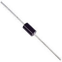
NTE6407 NTE ELECTRONICS, NTE6407 Datasheet

NTE6407
Manufacturer Part Number
NTE6407
Description
Replacement Semiconductors BiLat Trigger DO7
Manufacturer
NTE ELECTRONICS
Datasheet
1.NTE6407.pdf
(2 pages)
Specifications of NTE6407
Breakover Voltage Range
24V To 32V
Breakover Current Max.
25µA
Thyristor Case
DO-35
No. Of Pins
2
Current Rating
2A
Mounting Type
Through Hole
Package / Case
DO-7
Lead Free Status / RoHS Status
Lead free / RoHS Compliant
Lead Free Status / RoHS Status
Lead free / RoHS Compliant
Description:
The NTE6407 thru NTE6412 are bilateral trigger DIACs offering a range of voltage characteristics
from 28V to 63V. These devices are triggered from a blocking–to–conduction state for either polarity
of applied voltage whenever the amplitude of applied voltage exceeds the breakover voltage rating
of the DIAC.
Features:
D Glass–Chip Passivation
D DO35 Type Trigger Package
D Wide Voltage Range Selection
Absolute Maximum Ratings:
Maximum Trigger Firing Capacitance
Device Dissipation (T
Operating Junction Temperature Range, T
Storage Temperature Range, T
Thermal Resistance, Junction–to–Ambient, R
Thermal Resistance, Junction–to–Lead (Note 1), R
Lead Temperature (During Soldering, 1/16” (1.59mm) from case, 10sec max), T
Note 1. Based on maximum lead temperature of +85 C at
Electrical Characteristics: (T
Note 2. V
Breakover Voltage (Forward and Reverse)
Breakover Voltage Symmetry
NTE6408
NTE6411
NTE6412
NTE6411
NTE6412
NTE6407
NTE6407, NTE6408
Derate Above +40 C
BO
Parameter
= [ |+V
A
BO
= –40 to +40 C), P
| – |–V
Bilateral Trigger Diodes (DIACS)
. . . . . . . . . . . . . . . . . . . . . . . . . . . . . . . . . . . . . . . . . . . . . . . . . . . .
BO
stg
C
= +25 C unless otherwise specified)
| ].
. . . . . . . . . . . . . . . . . . . . . . . . . . . . . . . . . . . . . . . . . .
NTE6407, NTE6408,
NTE6411, NTE6412
Symbol
. . . . . . . . . . . . . . . . . . . . . . . . . . . . . . . . . . . . . . . . . . . . . . .
V
V
BO
BO
j
D
. . . . . . . . . . . . . . . . . . . . . . . . . . . . . . . . . .
. . . . . . . . . . . . . . . . . . . . . . . . . . . . . . . . . . . . . . . .
thJA
Note 2
. . . . . . . . . . . . . . . . . . . . . . . . . . . . . . . . . .
thJL
Test Conditions
. . . . . . . . . . . . . . . . . . . . . . . . . . . . .
250mW.
Min
24
28
35
56
–
–
–
L
. . . . . . . .
Typ
–40 to +125 C
–40 to +125 C
28
32
40
63
–
–
–
3.6mW/ C
Max Unit
32
36
45
70
278 C/W
100 C/W
2
3
4
250mW
+230 C
0.1 F
V
V
V
V
V
V
V
Related parts for NTE6407
NTE6407 Summary of contents
Page 1
... Bilateral Trigger Diodes (DIACS) Description: The NTE6407 thru NTE6412 are bilateral trigger DIACs offering a range of voltage characteristics from 28V to 63V. These devices are triggered from a blocking–to–conduction state for either polarity of applied voltage whenever the amplitude of applied voltage exceeds the breakover voltage rating of the DIAC ...
Page 2
... Electrical Characteristics (Cont’d): (T Parameter Dynamic Breakback Voltage NTE6407, NTE6408 NTE6411 NTE6412 Peak Breakover Current Peak Pulse Current NTE6407, NTE6408, NTE6411 NTE6412 Note 3. Typical switching time is 900ns measured at I 1.100 (27.9) .030 (.726) = +25 C unless otherwise specified) C Symbol Test Conditions 10mA, Note 3 ...


