NTE132 NTE ELECTRONICS, NTE132 Datasheet
NTE132
Manufacturer Part Number
NTE132
Description
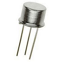
Replacement Semiconductors TO-106 N-CH JFET MXR
Manufacturer
NTE ELECTRONICS
Datasheet
1.NTE132.pdf
(2 pages)
Specifications of NTE132
Breakdown Voltage Vbr
-25V
Gate-source Cutoff Voltage Vgs(off) Max
-8V
Power Dissipation Pd
200mW
Operating Temperature Range
-55°C To +150°C
No. Of Pins
3
Transistor Polarity
N Channel
Continuous Drain Current Id
2mA
Lead Free Status / RoHS Status
Lead free / RoHS Compliant
Lead Free Status / RoHS Status
Lead free / RoHS Compliant


Absolute Maximum Ratings: (T
Drain–Gate Voltage, V
Gate–Source Voltage, V
Gate Current, I
Total Device Dissipation (T
Operating Junction Temperature Range, T
Storage Temperature Range, T
Lead Temperature (During Soldering, 1/16” from case for 10sec), T
Electrical Characteristics: (T
Gate–Source Breakdown Voltage
Gate Reverse Current
Gate–Source Cutoff Voltage
Gate–Source Voltage
Zero–Gate–Voltage Drain Current
Forward Transconductance
Forward Transfer Admittance
Output Admittance
Derate Above 25 C
Parameter
G
. . . . . . . . . . . . . . . . . . . . . . . . . . . . . . . . . . . . . . . . . . . . . . . . . . . . . . . . . . . . . . . . . .
DG
Silicon N–Channel JFET Transistor
GS
. . . . . . . . . . . . . . . . . . . . . . . . . . . . . . . . . . . . . . . . . . . . . . . . . . . . . . . . . . . .
A
. . . . . . . . . . . . . . . . . . . . . . . . . . . . . . . . . . . . . . . . . . . . . . . . . . . . . . .
. . . . . . . . . . . . . . . . . . . . . . . . . . . . . . . . . . . . . . . . . . . . . . . . . . . . . . . . .
= 25 C), P
stg
A
= +25 C unless otherwise specified)
V
A
Symbol
V
VHF Amplifier, Mixer
(BR)GSS
. . . . . . . . . . . . . . . . . . . . . . . . . . . . . . . . . . . . . . . . . .
I
GS(off)
I
|y
V
= +25 C unless otherwise specified)
|y
GSS
DSS
g
GS
os
fs
fs
|
|
D
. . . . . . . . . . . . . . . . . . . . . . . . . . . . . . . . . . . . . . . . . .
J
I
V
V
I
I
V
V
V
V
G
D
D
NTE132
GS
GS
DS
DS
DS
DS
. . . . . . . . . . . . . . . . . . . . . . . . . . . . . . . . . .
= 1 A, V
= 2nA, V
= 50 A, V
= 15V, V
= 15V, V
= 15V, V
= 15V, V
= 15V, V
= 15V, V
Test Conditions
DS
DS
DS
GS
GS
GS
GS
DS
DS
= 15V
= 0
= 15V
= 0
= 0, T
= 0
= 0, f = 1kHz
= 0, f = 100MHz
= 0, f = 1kHz
A
= +100 C
L
. . . . . . . . . . . . . . . . . . .
2500
2000
–0.5
Min
–25
–
–
–
2
–
Typ
–
–
–
–
–
–
–
–
–
–55 to +150 C
–55 to +150 C
7000
Max
–7.5
–2
–2
–8
20
50
–
–
2mW/ C
200mW
+260 C
10mA
Unit
–25V
mA
mho
mho
mho
nA
nA
V
V
V
25V
Related parts for NTE132
Image
Part Number
Description
Manufacturer
Datasheet
Request
R

Part Number:
Description:
TRANSISTOR,BJT,NPN,20V V(BR)CEO,500MA I(C),SIP
Manufacturer:
NTE ELECTRONICS

Part Number:
Description:
ICS,NTE LED FLASHLIGHTS,ICS,RED TRAFFIC AND SAFETY WAND FOR LW-PRO4000-BLK. MOLDED TRANSLUCENT PLASTIC WAND,TASK LIGHTING,LIGHTWAVE? LED FLASHLIGHTS ,NTE ELECTRONICS
Manufacturer:
NTE ELECTRONICS

Part Number:
Description:
Fuse; Non-Resettable; 15A; Dims 0.16x0.457"; Axial; 120-277VAC; PCB; NTE Series
Manufacturer:
NTE Electronics, Inc.
Datasheet:
Part Number:
Description:
Fuse; Non-Resettable; 15A; Dims 0.16x0.457"; Axial; 120-277VAC; PCB; NTE Series
Manufacturer:
NTE Electronics, Inc.
Datasheet:
Part Number:
Description:
Fuse; Non-Resettable; 15A; Dims 0.16x0.457"; Axial; 120-277VAC; PCB; NTE Series
Manufacturer:
NTE Electronics, Inc.
Datasheet:
Part Number:
Description:
Fuse; Non-Resettable; 15A; Dims 0.16x0.457"; Axial; 120-277VAC; PCB; NTE Series
Manufacturer:
NTE Electronics, Inc.
Datasheet:
Part Number:
Description:
Fuse; Non-Resettable; 15A; Dims 0.16x0.457"; Axial; 120-277VAC; PCB; NTE Series
Manufacturer:
NTE Electronics, Inc.
Datasheet:
Part Number:
Description:
Fuse; Non-Resettable; 15A; Dims 0.16x0.457"; Axial; 120-277VAC; PCB; NTE Series
Manufacturer:
NTE Electronics, Inc.
Datasheet:
Part Number:
Description:
Fuse; Non-Resettable; 15A; Dims 0.16x0.457"; Axial; 120-277VAC; PCB; NTE Series
Manufacturer:
NTE Electronics, Inc.
Datasheet:
Part Number:
Description:
Fuse; Non-Resettable; 15A; Dims 0.16x0.457"; Axial; 120/250VAC; PCB; NTE Series
Manufacturer:
NTE Electronics, Inc.
Datasheet:
Part Number:
Description:
MOTOR START AC ELECTROLYTIC
Manufacturer:
NTE [NTE Electronics]
Datasheet:
Part Number:
Description:
SOLID TANTALUM
Manufacturer:
NTE [NTE Electronics]
Datasheet:
Part Number:
Description:
HIGH-FREQ ALUMINUM ELECTROLYTIC
Manufacturer:
NTE [NTE Electronics]
Datasheet:
Part Number:
Description:
SNAP-IN MOUNT ALUMINUM ELECTROLYTIC
Manufacturer:
NTE [NTE Electronics]
Datasheet:

Part Number:
Description:
Replacement Semiconductors TO-220 NPN PWR AMP
Manufacturer:
NTE ELECTRONICS
Datasheet:
NTE132 Summary of contents
Page 1
... Lead Temperature (During Soldering, 1/16” from case for 10sec), T Electrical Characteristics: (T Parameter Gate–Source Breakdown Voltage Gate Reverse Current Gate–Source Cutoff Voltage Gate–Source Voltage Zero–Gate–Voltage Drain Current Forward Transconductance Forward Transfer Admittance Output Admittance NTE132 VHF Amplifier, Mixer = +25 C unless otherwise specified C ...
Page 2
Min Seating Plane .018 (0.45) Source .207 (5.28) Dia .180 (4.57) .500 (12.7) Min .100 (2.54) Dia Drain Gate ...