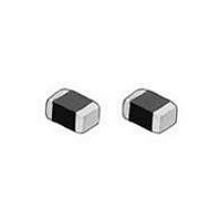
NCP18XH103F03RB Murata, NCP18XH103F03RB Datasheet - Page 21

NCP18XH103F03RB
Manufacturer Part Number
NCP18XH103F03RB
Description
Thermistors - NTC 10K OHM 1%
Manufacturer
Murata
Type
NTCr
Series
NTCr
Datasheet
1.NCP15WF104J03RC.pdf
(47 pages)
Specifications of NCP18XH103F03RB
Resistance
10 KOhms
Tolerance
1 %
Termination Style
SMD/SMT
Operating Temperature Range
- 40 C to + 125 C
Dimensions
0.80 mm W x 1.60 mm L
Package / Case
0603
Current Rating
0.31 mAmp
Power Rating
100 mW
Lead Free Status / RoHS Status
Lead free / RoHS Compliant
Available stocks
Company
Part Number
Manufacturer
Quantity
Price
Company:
Part Number:
NCP18XH103F03RB
Manufacturer:
Murata
Quantity:
600 000
Company:
Part Number:
NCP18XH103F03RB
Manufacturer:
MURATA
Quantity:
240 000
Part Number:
NCP18XH103F03RB
Manufacturer:
MURATA/村田
Quantity:
20 000
!Note
• This PDF catalog is downloaded from the website of Murata Manufacturing co., ltd. Therefore, it’s specifications are subject to change or our products in it may be discontinued without advance notice. Please check with our
• This PDF catalog has only typical specifications because there is no space for detailed specifications. Therefore, please approve our product specifications or transact the approval sheet for product specifications before ordering.
sales representatives or product engineers before ordering.
!Note
1. Mounting Position
2. Allowable Soldering Temperature and Time
(a) Solder within the temperature and time combinations
(b) Excessive soldering conditions may cause dissolution of
(c) In case of repeated soldering, the accumulated soldering
1
Notice (Soldering and Mounting)
Choose a mounting position that minimizes the stress
imposed on the chip during flexing or bending of the
board.
indicated by the slanted lines in the following graphs.
metallization or deterioration of solder-wetting on the
external electrode.
time should be within the range shown in the figure
below. (For example, Reflow peak temperature: 260 C,
twice -> The total accumulated soldering time at 260 C is
within 30 seconds.)
NCP18/21 Series
Allowable Flow Soldering Temp. and Time
• Please read rating and !CAUTION (for storage, operating, rating, soldering, mounting and handling) in this catalog to prevent smoking and/or burning, etc.
• This catalog has only typical specifications because there is no space for detailed specifications. Therefore, please approve our product specifications or transact the approval sheet for product specifications before ordering.
280
270
260
250
240
230
220
210
0
Time (sec.)
10
Temp. Sensor and Compensation Chip Type !Caution/Notice
20
30
Component Direction
Mounting Close to Board Separation Line
NCP03/15 Series
Allowable Reflow Soldering Temp. and Time
Allowable Reflow Soldering Temp. and Time
Perforation
Holes
280
270
260
250
240
230
220
280
270
260
250
240
230
220
210
0
0
A
10
10
Slit
20 30 40 50 60 70
B
20 30 40 50 60 70 80
Time (sec.)
Time (sec.)
D
C
Continued on the following page.
Keep this product on the
PC Board away from the
Separation Line.
Worst
80
90
A-C-B-D
Locate this
product
horizontal to the
direction in
which stress
acts.
100
110
90
Better
R44E.pdf
19
11.2.21
4


