ANT-2.4-PW-QW Antenna Factor, ANT-2.4-PW-QW Datasheet
ANT-2.4-PW-QW
Manufacturer Part Number
ANT-2.4-PW-QW
Description
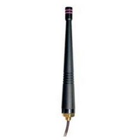
Antennas Permanent Mount 1/2 Wave Whip 2.4GHz
Manufacturer
Antenna Factor
Datasheet
1.ANT-2.4-PW-QW.pdf
(1 pages)
Specifications of ANT-2.4-PW-QW
Dimensions
105 mm L x 14.5 mm W
Impedance
50 Ohms
Mounting Style
Through Hole
Technology Type
1/2 Wave Whip
Frequency
2.45 GHz
Bandwidth
250 MHz
Termination Style
Screw
Lead Free Status / RoHS Status
Lead free / RoHS Compliant
(105.0)
4.13”
Product Dimensions
1/4-28
7/16”
HEX
UNF
(13.5)
0.53”
(14.5)
0.57”
Antenna Factor 159 Ort Lane Merlin, OR 97532 www.antennafactor.com
End View
0.31”
(7.8)
0.20”
(5.0)
541-956-0931 (phone) 541-471-6251 (fax)
ANT-2.4-PW-QW DATA SHEET
Electrical specifications and plots measured on 4.00” x 4.00” reference ground plane
• Low cost
• Outstanding performance
• Omni-directional pattern
• Wide bandwidth
• Flexible main shaft
• Rugged & weatherized
• Integral 8½-inch RG-174 coax cable
• Use with plastic or metal enclosures
• Center Freq.
• Bandwidth
• Wavelength
• VSWR
• Impedance
• Connection
• Cable
• ANT-2.4-PW-QW
Description
Features
Electrical Specifications
Ordering Information
VSWR Graph
Designed for permanent attachment, PW Series 1/2-
wave whips give outstanding performance in a rugged
and cost-effective package. The antenna is attached by
placing its base through a 1/4” hole in the product and
securing it with a nut or by threading it into a PEM-style
insert. This method of attachment is highly secure and
saves the cost of an antenna connector. The antenna is
fed through the base with RG-174 coax cable, which may
be soldered directly to the board or attached using a 50-
ohm connector. Standard cable length is 8.5”. Custom
lengths and terminations are available by special order.
S11 SWR
CENTER 2450.000MHz
2.45GHz
250MHz
1/2-wave
<1.9 typ. at center
50 ohms
Case-mount
8½-inch RG-174 coax
Typical VSWR
SPAN 200.000MHz
1.373
Rev 4-13-09
Related parts for ANT-2.4-PW-QW
Image
Part Number
Description
Manufacturer
Datasheet
Request
R

Part Number:
Description:
ANTENNA 2.45GHZ 1/4 WAVE RP/SMA
Manufacturer:
Linx Technologies Inc
Datasheet:

Part Number:
Description:
ANTENNA 2.45GHZ 1/4WAVE RA RPSMA
Manufacturer:
Linx Technologies Inc
Datasheet:

Part Number:
Description:
ANTENNA 2.4GHZ RA 1/4 WAVE WHIP
Manufacturer:
Linx Technologies Inc
Datasheet:

Part Number:
Description:
ANTENNA 2.4GHZ RA 1/4 WAVE SMA
Manufacturer:
Linx Technologies Inc
Datasheet:

Part Number:
Description:
ANTENNA 2.4GHZ 1/2 WAVE RP/SMA
Manufacturer:
Linx Technologies Inc
Datasheet:

Part Number:
Description:
ANTENNA 2.45GHZ 1/4 WAVE SMA
Manufacturer:
Linx Technologies Inc
Datasheet:

Part Number:
Description:
Antennas RPSMA Tilt Swivel 1/2 WaveWhip 2.45GHz
Manufacturer:
Antenna Factor
Datasheet:

Part Number:
Description:
Antennas RPSMA 1/2 Wave Dipole Whip 2.45 GHz
Manufacturer:
Antenna Factor
Datasheet:

Part Number:
Description:
Antennas 2.45GHz Corner Antenna N Connector
Manufacturer:
Antenna Factor
Datasheet:

Part Number:
Description:
Antennas Omni-Directional Ant 2.4Ghz 7dBi Gain
Manufacturer:
Antenna Factor
Datasheet:

Part Number:
Description:
Antennas Perm Mnt Reducd Ht 1/4 Wave Whip 2.4GHz
Manufacturer:
Antenna Factor
Datasheet:

Part Number:
Description:
Antennas SMA RAngl Reducd Ht 1/4 Wave Whip 2.4GHz
Manufacturer:
Antenna Factor
Datasheet:
Part Number:
Description:
Antennas RPSMA RAng Reducd Ht 1/4 Wave Whip 2.4GHz
Manufacturer:
Antenna Factor
Datasheet:
Part Number:
Description:
ANTENNA 2.4GHZ 1/2WAV WHIP SMA
Manufacturer:
Linx Technologies Inc
Datasheet:
