DE1E3KX222MA4BL01 Murata, DE1E3KX222MA4BL01 Datasheet - Page 26
DE1E3KX222MA4BL01
Manufacturer Part Number
DE1E3KX222MA4BL01
Description
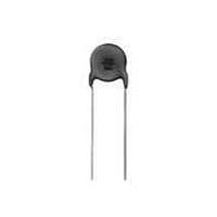
Ceramic Disc Capacitors 2200pF 20%
Manufacturer
Murata
Specifications of DE1E3KX222MA4BL01
Voltage Rating
250 Volts
Operating Temperature Range
- 25 C to + 125 C
Termination Style
Radial
Product
High Voltage Ceramic Disc Capacitors
Dimensions
9 mm Dia.
Capacitance
2200 pF
Tolerance
20 %
Temperature Coefficient
E
Lead Spacing
10 mm
Lead Free Status / RoHS Status
Lead free / RoHS Compliant
Available stocks
Company
Part Number
Manufacturer
Quantity
Price
Company:

Part Number:
DE1E3KX222MA4BL01
Manufacturer:
MURATA
Quantity:
10 000
Part Number:
DE1E3KX222MA4BL01
Manufacturer:
MURATA/村田
Quantity:
20 000


!Note
• This PDF catalog is downloaded from the website of Murata Manufacturing co., ltd. Therefore, it’s specifications are subject to change or our products in it may be discontinued without advance notice. Please check with our
• This PDF catalog has only typical specifications because there is no space for detailed specifications. Therefore, please approve our product specifications or transact the approval sheet for product specifications before ordering.
sales representatives or product engineers before ordering.
!Note
1. Operating Voltage
2. Operating Temperature and Self-generated Heat
3. Test Condition for Withstanding Voltage
(1) Test Equipment
!Caution (Rating)
When DC-rated capacitors are to be used in AC or ripple
current circuits, be sure to maintain the Vp-p value of the
applied voltage or the Vo-p which contains DC bias within
the rated voltage range.
When the voltage is applied to the circuit, starting or
stopping may generate irregular voltage for a transit
period because of resonance or switching. Be sure to
use a capacitor with a rated voltage range that includes
these irregular voltages.
(Apply to B/E/F Char.)
Keep the surface temperature of a capacitor below the
upper limit of its rated operating temperature range. Be
sure to take into account the heat generated by the
capacitor itself. When the capacitor is used in a high-
frequency current, pulse current or similar current, it may
have self-generated heat due to dielectric loss. Applied
voltage load should be such that self-generated heat is
within 20 C under the condition where the capacitor is
subjected at an atmosphere temperature of 25 C. When
measuring, use a thermocouple of small thermal
capacity-K of ø0.1mm under conditions where the
capacitor is not affected by radiant heat from other
components or wind from surroundings. Excessive heat
may lead to deterioration of the capacitor's characteristics
and reliability. (Never attempt to perform measurement
with the cooling fan running. Otherwise, accurate
measurement cannot be ensured.)
Test equipment for AC withstanding voltage should be
used with the performance of the wave similar to
50/60Hz sine wave.
If the distorted sine wave or overload exceeding the
specified voltage value is applied, a defect may be
caused.
Positional
Measurement
• Please read rating and !CAUTION (for storage, operating, rating, soldering, mounting and handling) in this catalog to prevent smoking and/or burning, etc.
• This catalog has only typical specifications because there is no space for detailed specifications. Therefore, please approve our product specifications or transact the approval sheet for product specifications before ordering.
Voltage
V
0
-p
DC Voltage
V
DC+AC Voltage
0
-p
Safety Recognized Ceramic Capacitors !Caution
Vp-p
AC Voltage
Vp-p
Pulse Voltage (1)
Continued on the following page.
Vp-p
Pulse Voltage (2)
C85E.pdf
25
06.6.1
5
Related parts for DE1E3KX222MA4BL01
Image
Part Number
Description
Manufacturer
Datasheet
Request
R

Part Number:
Description:
Murata Microblower 20x20 DCDC Driver Board - Samples Only
Manufacturer:
Murata
Part Number:
Description:
357-036-542-201 CARDEDGE 36POS DL .156 BLK LOPRO
Manufacturer:
Murata
Datasheet:
Part Number:
Description:
Manufacturer:
Murata
Datasheet:
Part Number:
Description:
Manufacturer:
Murata
Datasheet:
Part Number:
Description:
Manufacturer:
Murata
Datasheet:
Part Number:
Description:
Manufacturer:
Murata
Datasheet:
Part Number:
Description:
Manufacturer:
Murata
Datasheet:
Part Number:
Description:
Manufacturer:
Murata
Datasheet:
Part Number:
Description:
Manufacturer:
Murata
Datasheet:
Part Number:
Description:
BLM21BD751SN1On-Board Type (DC) EMI Suppression Filters
Manufacturer:
Murata
Datasheet:
Part Number:
Description:
BLM15AG100SN1On-Board Type (DC) EMI Suppression Filters
Manufacturer:
Murata
Datasheet:
Part Number:
Description:
NFE31PT222Z1E9On-Board Type (DC) EMI Suppression Filters
Manufacturer:
Murata
Datasheet:
Part Number:
Description:
Chip Coil
Manufacturer:
Murata
Datasheet:
Part Number:
Description:
Chip Coil
Manufacturer:
Murata
Datasheet: