ZJYS81R5-2PL51-G01 TDK Corporation, ZJYS81R5-2PL51-G01 Datasheet
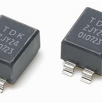
ZJYS81R5-2PL51-G01
Manufacturer Part Number
ZJYS81R5-2PL51-G01
Description
Common Mode Inductors 1000ohms 10MHz 80V
Manufacturer
TDK Corporation
Series
ZJYSr
Datasheet
1.ZJYS81R5-2PL25T-G01.pdf
(2 pages)
Specifications of ZJYS81R5-2PL51-G01
Dimensions
5 mm W x 9 mm L x 6 mm H
Lead Spacing
2.54 mm
Product
Inductors
Shielding
Unshielded
Inductance
1.5 uH
Maximum Dc Current
0.5 Amp
Maximum Dc Resistance
0.3 Ohms
Operating Temperature Range
- 40 C to + 125 C
Termination Style
SMD/SMT
Lead Free Status / RoHS Status
Lead free / RoHS Compliant
Available stocks
Company
Part Number
Manufacturer
Quantity
Price

Part Number:
ZJYS81R5-2PL51-G01
Manufacturer:
TDK/东电化
Quantity:
20 000


Common Mode Filters(SMD)
For CAN-BUS / General Signal Line
ZJYS Series ZJYS81 Type
FEATURES
• Operating temperature range covers from –40 to +125°C.
• Non-dissolution of the abutment amounts in circuit board mount-
• The products contain no lead and also support lead-free solder-
• This product conforms to the standards that are slated to be
APPLICATIONS
CAN-BUS system, facsimiles, modems, ISDN
PACKAGING STYLE AND QUANTITIES
Packaging style
Taping
SHAPES AND DIMENSIONS
ELECTRICAL CHARACTERISTICS
Part No.
ZJYS81R5-2P24-G01
ZJYS81R5-2P50-G01
ZJYS81R5-2PL25-G01
ZJYS81R5-2PL51-G01
TYPICAL ELECTRICAL CHARACTERISTICS
IMPEDANCE vs. FREQUENCY CHARACTERISTICS
ZJYS81R5-2P24
• Conformity to RoHS Directive: This means that, in conformity with EU Directive 2002/95/EC, lead, cadmium, mercury, hexavalent chromium, and specific
• All specifications are subject to change without notice.
1
2
100000
bromine-based flame retardants, PBB and PBDE, have not been used, except for exempted applications.
ing.
ing.
introduced under the RoHS Directive.
10000
1000
0.6±0.2
100
7.1max.
10
9±0.5
1
Common mode
4
3
Differential mode
Frequency ( MHz )
10
Quantity
1500 pieces/reel
1.3
100
Common mode impedance
(Ω)[10MHz]
min.
500
1000
600
1000
2.54±0.25
1000
CIRCUIT DIAGRAM
• No polarity
1
2
ZJYS81R5-2P50
100000
typ.
1000
2000
1000
2000
10000
1000
Dimensions in mm
100
10
1
4
3
Weight: 0.4g
Common mode
Differential mode
Frequency ( MHz )
DC resistance
(Ω)max.
0.15
0.25
0.25
0.3
10
PRODUCT IDENTIFICATION
(1) Series name
(2) Number of line
(3) Winding type
(4) Product identification number
(5) Packaging style
(6) TDK internal code
ZJYS81R5 - 2P
2P: 2-line
L: Sector
No mark: Bifilar
T: ø330mm reel taping
(1)
100
RECOMMENDED PC BOARD PATTERN
Rated current
(A)max.
0.5
0.5
0.5
0.5
(2) (3) (4) (5)
6.7
9.9
1000
L
ZJYS81R5-2PL25
25 (T) - G01
100000
10000
1000
100
10
Insulation resistance
(MΩ)min.
100
100
100
100
Dimensions in mm
1
Common mode
001-08 / 20070118 / e971_zjys81.fm
(6)
Conformity to RoHS Directive
Frequency ( MHz )
10
Differential mode
Rated voltage
(V)max.
80
80
80
80
100
(1/2)
1000
Related parts for ZJYS81R5-2PL51-G01
Image
Part Number
Description
Manufacturer
Datasheet
Request
R

Part Number:
Description:
CHOKE COMM MODE 1000 OHM .5A SMD
Manufacturer:
TDK Corporation
Datasheet:
Part Number:
Description:
CHOKE COMM MODE 600 OHM .5A SMD
Manufacturer:
TDK Corporation
Datasheet:

Part Number:
Description:
Common Mode Inductors ZJYS81R5-2PL-51T-G01
Manufacturer:
TDK Corporation
Datasheet:
Part Number:
Description:
Common Mode Inductors 600ohms 10MHz 80V
Manufacturer:
TDK Corporation
Datasheet:

Part Number:
Description:
Manufacturer:
TDK Corporation
Datasheet:
Part Number:
Description:
TDK DC to DC Converters, DC to AC Inverters
Manufacturer:
TDK Corporation
Datasheet:
Part Number:
Description:
TDK DC to DC Converters, DC to AC Inverters
Manufacturer:
TDK Corporation
Datasheet:
ZJYS81R5-2PL51-G01 Summary of contents
Page 1
... ELECTRICAL CHARACTERISTICS Common mode impedance (Ω)[10MHz] Part No. min. ZJYS81R5-2P24-G01 500 ZJYS81R5-2P50-G01 1000 ZJYS81R5-2PL25-G01 600 ZJYS81R5-2PL51-G01 1000 TYPICAL ELECTRICAL CHARACTERISTICS IMPEDANCE vs. FREQUENCY CHARACTERISTICS ZJYS81R5-2P24 100000 10000 Common mode 1000 100 Differential mode 100 1000 Frequency ( MHz ) • ...
Page 2
TYPICAL ELECTRICAL CHARACTERISTICS IMPEDANCE vs. FREQUENCY CHARACTERISTICS 100000 10000 Common mode 1000 Differential mode 100 100 1000 Frequency ( MHz ) • All specifications are subject to change without notice. (2/2) 001-08 / 20070118 / e971_zjys81.fm ...