280-CR5-820-RC Xicon, 280-CR5-820-RC Datasheet - Page 2
280-CR5-820-RC
Manufacturer Part Number
280-CR5-820-RC
Description
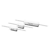
Wirewound Resistors - Through Hole 820ohms 5% Tol
Manufacturer
Xicon
Series
CRr
Type
Cement Power Resistorr
Datasheet
1.280-CR15-1.1-RC.pdf
(2 pages)
Specifications of 280-CR5-820-RC
Resistance
820 Ohms
Tolerance
5 %
Power Rating
5 Watts
Termination Style
Axial
Operating Temperature Range
- 55 C to + 155 C
Dimensions
10 mm W x 22 mm L x 9 mm H
Product
Power Resistors Wire Wound Cement Filled Ceramic
Temperature Coefficient
+/- 350 PPM / C
Lead Free Status / RoHS Status
Lead free / RoHS Compliant


XC-600041
Cement Power Resistors (RoHS Compliant)
No.
Characteristics
Temperature
coefficient
Dielectric
withstanding
voltage
Temperature
cycling
Short time
overload
Load life in
humidity
Load life
Terminal strength
Resistance to
soldering heat
Solderability
1
2
3
4
5
6
CONSTRUCTION
CHARACTERISTICS
Specifications are subject to change without notice. No liability or warranty implied by this information. Environmental compliance based on producer documentation.
Resistance wire
Filling Materials
Subpart Name
Ceramic Case
End Cap
Body
Lead
(Electrosolder plated surface) Pb Free
Tin plated iron surface
Annealed copper wire
Rod Type Ceramics
Quartz mixed sand
XICON PASSIVE COMPONENTS • (800) 628-0544
Ni-Cr Alloy
Material
Ceramic
± 350 PPM / °C Max.
<20Ω ± 400 PPM / °C
No evidence of flashover,
mechanical damage, arcing
or insulation break down
Resistance change rate is
± (2% + 0.05Ω) Max. with no
evidence of mechanical damage
Resistance change rate is
± (5% + 0.05Ω) Max. with no
evidence of mechanical damage
Resistance value
Wire-wound
Resistance value
Wire-wound
No evidence of mechanical
damage
Resistance change rate is
± (1% + 0.05ø) Max. with no
evidence of mechanical damage
95 % coverage Min.
Limits
± 5%
± 5%
∆ R/R
∆ R/R
Material Generic Name
Tin-Coated Copper wire
Tin : 5%, Iron : 95%
Al
Al
Ni-Cr Alloy
2
2
O
O
SiO
3
3
, SiO
, SiO
2
2
2
5.2 Natural resistance change per temp.
degree centigrade.
R
R
R
5.7 Resistors shall be clamped in the trough
of a 90° metallic V-block and shall be tested at
AC potential respectively for 60 +10/ -0 secs.
7.4 Resistance change after continuous
5 cycles for duty shown below:
5.5 Permanent resistance change after the
application of a potential of 2.5 times RCWV
for 5 seconds
7.9 Resistance change after 1,000 hours
operating at RCWV with duty cycle of
(1.5 hours "on", 0.5 hour "off") in a humidity test
chamber controlled at 40 °C ± 2 °C and 90 to 95 %
relative humidity
7.10 Permanent resistance change after
1,000 hours operating at RCWV with duty cycle
of (1.5 hours “on”, 0.5 hour “off”)
at 70 °C ±2 °C
6.1 Direct load :
Resistance to a 2.5 kgs direct load for 10 secs.
in the direction of the longitudinal axis of the
terminal leads
Twist test :
Terminal leads shall be bent through 90 ° at
a point of about 6mm from the body of the
resistor and shall be rotated through 360°
about the original axis of the bent terminal in
alternating direction for a total of 3 rotations
6.4 Permanent resistance change when leads
immersed to 3.2 to 4.8 mm from the body in
350 °C ± 10 °C solder for 3 ± 0.5 secs.
6.5 The area covered with a new , smooth
clean , shiny and continuous surface free
from concentrated pinholes.
R
Step
1
1
2
2
(t
: Resistance value at room temperature (t
: Resistance value at room temp. plus 100 °C (t
1
2
3
4
-R
2
-t
1
1
)
Test temp. of solder : 245 °C ± 3 °C
Dwell time in solder : 2 ~ 3 seconds
Test Methods ( JIS C 5201-1 )
3
x10
6
+155 °C ± 2 °C
-55 °C ± 3 °C
Temperature
Room temp.
Room temp.
(PPM / °C)
Cement: Wire wound
4
PW-RC Series
6
5 2
Date Revised: 9/28/05
1
1
)
10 ~ 15 mins
10 ~ 15 mins
30 mins
30 mins
Time
2
)
Related parts for 280-CR5-820-RC
Image
Part Number
Description
Manufacturer
Datasheet
Request
R

Part Number:
Description:
Wirewound Resistors USE 280-CR5-0.43-RC 5% Tol
Manufacturer:
Xicon
Part Number:
Description:
Wirewound Resistors USE 280-CR5-360-RC 5% Tol
Manufacturer:
Xicon

Part Number:
Description:
Wirewound Resistors - Through Hole 330ohms 5% Tol
Manufacturer:
Xicon
Datasheet:
Part Number:
Description:
Wirewound Resistors - Through Hole 500ohms 5% Tol
Manufacturer:
Xicon
Datasheet:
Part Number:
Description:
Wirewound Resistors - Through Hole 3.6ohms 5% Tol
Manufacturer:
Xicon
Datasheet:
Part Number:
Description:
Wirewound Resistors - Through Hole 91ohms 5% Tol
Manufacturer:
Xicon
Datasheet:

Part Number:
Description:
Standard LED - Through Hole Red Water Clear
Manufacturer:
Xicon
Datasheet:

Part Number:
Description:
Standard LED - Through Hole Yellow Water Clear
Manufacturer:
Xicon
Datasheet:

Part Number:
Description:
Standard LED - Through Hole Blink Red Diffused
Manufacturer:
Xicon
Datasheet:

Part Number:
Description:
Standard LED - Through Hole Green Diffused
Manufacturer:
Xicon
Datasheet:
Part Number:
Description:
Standard LED - Through Hole Blue Water Clear
Manufacturer:
Xicon
Datasheet: