VLF302510MT-1R0N TDK Corporation, VLF302510MT-1R0N Datasheet

INDUCTOR POWER 1.0UH 2.0A SMD

VLF302510MT-1R0N

Manufacturer Part Number
VLF302510MT-1R0N
Description
INDUCTOR POWER 1.0UH 2.0A SMD
Manufacturer
TDK Corporation
Series
VLF-MTr
Datasheet

Specifications of VLF302510MT-1R0N

Inductance
1µH
Tolerance
±30%
Shielding
Shielded
Package / Case
0.118" L x 0.098" W x 0.039" H (3.00mm x 2.50mm x 1.00mm)
Current
2A
Operating Temperature
-40°C ~ 105°C
Frequency - Test
1MHz
Applications
Power Line
Current - Saturation
2.22A
Current - Temperature Rise
2.13A
Dc Resistance (dcr)
40 mOhm Max
Mounting Type
Surface Mount
Test Frequency
1 MHz
Maximum Dc Current
2 Amps
Maximum Dc Resistance
0.04 Ohms
Dimensions
2.5 mm W x 3 mm L x 1 mm H
Operating Temperature Range
- 40 C to + 105 C
Termination Style
SMD/SMT
Lead Free Status / RoHS Status
Lead free / RoHS Compliant
Q @ Freq
-
Self Resonant Freq
-
Lead Free Status / RoHS Status
Lead free / RoHS Compliant, Lead free / RoHS Compliant
Other names
445-6769-2

Available stocks

Company
Part Number
Manufacturer
Quantity
Price
Part Number:
VLF302510MT-1R0N
Manufacturer:
TDK
Quantity:
42 000
Part Number:
VLF302510MT-1R0N
Manufacturer:
TDK/东电化
Quantity:
20 000
SMD Inductors(Coils)
For Power Line(Wound, Magnetic Shielded)
VLF-MT Series VLF302510MT
With the VLF302510MT Series, a DC to DC converter with top-
class voltage conversion efficiency for similar size products was
achieved by optimizing the magnetic material and configuration.
These products are optimal for use as choke coils in switching
power supplies such as those in mobile devices requiring space-
saving design.
FEATURES
• Miniature size
• Generic use for portable DC to DC converter line.
• High magnetic shield construction should actualize high resolu-
• The products contain no lead and also support lead-free
• The products is halogen-free.
• It is a product conforming to RoHS directive.
APPLICATIONS
Smartphones, cellular phones, DSCs, DVCs, HDDs, LCD displays,
compact power supply modules, etc.
SHAPES AND DIMENSIONS
RECOMMENDED PC BOARD PATTERN
CIRCUIT DIAGRAM
• Conformity to RoHS Directive: This means that, in conformity with EU Directive 2002/95/EC, lead, cadmium, mercury, hexavalent chromium, and specific
• Please contact our Sales office when your application are considered the following:
• All specifications are subject to change without notice.
0.9
The device’s failure or malfunction may directly endanger human life (e.g. application for automobile/aircraft/medical/nuclear power devices, etc.)
bromine-based flame retardants, PBB and PBDE, have not been used, except for exempted applications.
Mount area: 3.0×2.5mm
Low profile: 1.0mm max. height
tion for EMC protection.
soldering.
2.5±0.2
0.8
0.9
Dimensions in mm
( 0.7 )
( 0.8 )
( 0.7 )
Dimensions in mm
Weight: 0.026g
PRODUCT IDENTIFICATION
(1) Series name
(2) Dimensions L×W×H mm max.
(3) Packaging style
(4) Inductance value
(5) Inductance tolerance
PACKAGING STYLE AND QUANTITIES
Packaging style
Taping
HANDLING AND PRECAUTIONS
• Before soldering, be sure to preheat components.
• When hand soldering, apply the soldering iron to the printed
RECOMMENDED SOLDERING CONDITION
REFLOW SOLDERING
VLF 302510M
(1)
250 to 260˚C
230˚C
180˚C
150˚C
The preheating temperature should be set so that the
temperature difference between the solder temperature and
product temperature does not exceed 150°C.
circuit board only. Temperature of the iron tip should not exceed
350°C. Soldering time should not exceed 3 seconds.
T
1R0
100
M
N
(2)
Preheating
60 to 120s
(3)
T - 1R0 N
Time(s)
(4) (5)
002-02 / 20101028 / e531_vlf302510mt.fm
Soldering
30 to 60s
10s max.
Taping
(Embossed carrier tape)
1.0µH
10µH
±20%
±30%
Quantity
2000 pieces/reel
Conformity to RoHS Directive
Natural
cooling
(1/3)

Related parts for VLF302510MT-1R0N

VLF302510MT-1R0N Summary of contents

Page 1

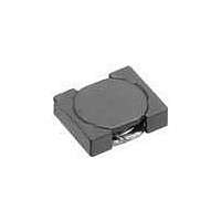
... SMD Inductors(Coils) For Power Line(Wound, Magnetic Shielded) VLF-MT Series VLF302510MT With the VLF302510MT Series converter with top- class voltage conversion efficiency for similar size products was achieved by optimizing the magnetic material and configuration. These products are optimal for use as choke coils in switching power supplies such as those in mobile devices requiring space- saving design ...

Page 2

... Rated current: Value obtained when current flows and the temperature has risen to 40°C or when DC current flows and the nominal value of inductance has fallen by 30%, whichever is smaller. • Operating temperature range: –40 to +105°C (Including self-temperature rise) TYPICAL ELECTRICAL CHARACTERISTICS INDUCTANCE vs. DC SUPERPOSITION CHARACTERISTICS VLF302510MT-1R0N 1.0 0.8 0.6 0.4 ...

Page 3

... DC current ( A ) C=20,000µ øD1 R3 Cover type Dimensions 3.3typ. 8.00± 0.2 3.50± 0 2.00±0.05 0.05 to 0.35 4.0±0.1 ø 1.2±0.2 0.25±0.05 0.3max. 002-02 / 20101028 / e531_vlf302510mt.fm (3/ 1.75± 0.1 øD0 1.5+0.1/–0 θ 5° typ. ...

Related keywords