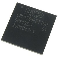
LPC1768FET100,551 NXP Semiconductors, LPC1768FET100,551 Datasheet - Page 47

LPC1768FET100,551
Manufacturer Part Number
LPC1768FET100,551
Description
IC MCU 32BIT 512KB FLASH 100LQFP
Manufacturer
NXP Semiconductors
Series
LPC17xxr
Datasheet
1.LPC1768FET100551.pdf
(79 pages)
Specifications of LPC1768FET100,551
Core Processor
ARM® Cortex-M3™
Core Size
32-Bit
Speed
100MHz
Connectivity
CAN, Ethernet, I²C, IrDA, Microwire, SPI, SSI, UART/USART, USB OTG
Peripherals
Brown-out Detect/Reset, DMA, I²S, Motor Control PWM, POR, PWM, WDT
Number Of I /o
70
Program Memory Size
512KB (512K x 8)
Program Memory Type
FLASH
Ram Size
64K x 8
Voltage - Supply (vcc/vdd)
2.4 V ~ 3.6 V
Data Converters
A/D 8x12b, D/A 1x10b
Oscillator Type
Internal
Operating Temperature
-40°C ~ 85°C
Package / Case
100-LQFP
Processor Series
LPC1768
Core
ARM Cortex-M3
Data Bus Width
32 bit
Data Ram Size
16 KB
Interface Type
Ethernet, USB, CAN, I2S, I2C
Maximum Clock Frequency
100 MHz
Number Of Programmable I/os
70
Number Of Timers
4
Maximum Operating Temperature
+ 150 C
Mounting Style
SMD/SMT
Lead Free Status / RoHS Status
Lead free / RoHS Compliant
Eeprom Size
-
Lead Free Status / Rohs Status
Details
Other names
568-5215
Available stocks
Company
Part Number
Manufacturer
Quantity
Price
Company:
Part Number:
LPC1768FET100,551
Manufacturer:
NXP Semiconductors
Quantity:
10 000
NXP Semiconductors
[5]
[6]
[7]
[8]
[9]
[10] On pin VBAT; I
[11] On pin VBAT; V
[12] All internal pull-ups disabled. All pins configured as output and driven LOW. V
[13] On pin V
[14] The ADC is powered if the PDN bit in the AD0CR register is set to 1. See LPC17xx user manual UM10360_1.
[15] The ADC is in Power-down mode if the PDN bit in the AD0CR register is set to 0. See LPC17xx user manual UM10360_1.
[16] V
[17] Including voltage on outputs in 3-state mode.
[18] V
[19] 3-state outputs go into 3-state mode in Deep power-down mode.
[20] Allowed as long as the current limit does not exceed the maximum current allowed by the device.
[21] To V
[22] Includes external resistors of 33 Ω ± 1 % on D+ and D−.
LPC1769_68_67_66_65_64_63
Product data sheet
Applies to LPC1768/67/66/65/64/63.
Applies to LPC1769 only.
IRC running at 4 MHz; main oscillator and PLL disabled; PCLK =
BOD disabled.
On pin V
of the PDN bit is set to 0.
i(VREFP)
DD(3V3)
SS
.
DDA
supply voltages must be present.
DD(REG)(3V3)
= 3.3 V; T
; V
10.1 Power consumption
DD(REG)(3V3)
DDA
BAT
= 3.3 V; T
amb
= 3.0 V; T
. I
BAT
= 25 °C.
Fig 7.
= 530 nA. V
= 630 nA; V
amb
amb
I
DD(Reg)(3V3)
= 25 °C. The ADC is powered if the PDN bit in the AD0CR register is set to 1 and in Power-down mode
= 25 °C.
(μA)
400
350
300
250
200
Conditions: V
Deep-sleep mode: typical regulator supply current I
temperature
−40
DD(REG)(3V3)
DD(REG)(3V3)
All information provided in this document is subject to legal disclaimers.
DD(Reg)(3V3)
= 3.0 V; V
= 3.0 V; V
−15
Rev. 7 — 5 April 2011
BAT
= 3.3 V; BOD disabled.
BAT
= 3.0 V; T
LPC1769/68/67/66/65/64/63
= 3.0 V; T
CCLK
⁄
10
8
.
amb
amb
= 25 °C.
DD(3V3)
= 25 °C.
32-bit ARM Cortex-M3 microcontroller
= 3.3 V; T
35
amb
DD(Reg)(3V3)
= 25 °C.
60
temperature (°C)
3.6 V
3.3 V
2.4 V
versus
002aaf568
© NXP B.V. 2011. All rights reserved.
85
47 of 79


