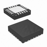
ISL59604IRZ Intersil, ISL59604IRZ Datasheet - Page 3

ISL59604IRZ
Manufacturer Part Number
ISL59604IRZ
Description
IC VIDEO EQUALIZER 20-QFN
Manufacturer
Intersil
Series
MegaQ™r
Type
Video Equalizerr
Datasheet
1.ISL59601IRZ-T7.pdf
(27 pages)
Specifications of ISL59604IRZ
Applications
Security Systems, Video Routing
Mounting Type
Surface Mount
Package / Case
20-VFQFN Exposed Pad
Rohs Compliant
Yes
Lead Free Status / RoHS Status
Lead free / RoHS Compliant
Pin Descriptions
INPUTS
OUTPUTS
DIGITAL I/O
SERIAL INTERFACE
PIN NUMBER PIN NAME
12
13
10
16
18
19
20
3
5
7
8
9
EQ_DISABLE Digital Input. Equalizer Disable.
VIDEO OUT Single-ended video output. The internal AGC sets this level to 2V
LOCKED
INVERT
FREEZE
ISL59601, ISL59602, ISL59603, ISL59604, ISL59605
COLOR
IN+
SEN
SCK
CFB
IN-
SD
3
High impedance analog input. This is the positive differential video input. Input signals are
externally AC-coupled with an external 1.0μF capacitor. See Applications Information section for
information regarding input network for Cat x and coax cables.
High impedance analog input. This is the negative differential video input. Input signals are
externally AC-coupled with an external 1.0μF capacitor. See Applications Information section for
information regarding input network for Cat x and coax cables.
Analog input. Bypass to ground with a 1500pF capacitor and connect to VIDEO OUT via a 0.022μF
capacitor in series with a 300Ω resistor.
(pre-cable) video source.
0: Normal Operation
1: Disables the equalizer to allow for insertion of upstream data onto the signal path, e.g. RS-485.
Digital I/O. Color Indicator/Override.
0: Monochrome
1: Color
When used as an output, this pin indicates whether the incoming signal does or does not have a
colorburst. When used as an input, this pin forces the state machine to into monochrome or color
mode. See Figure 49 and associated text for more information on functionality.
When COLOR is not externally driven, it is an output pin with a 13k (typical) output impedance. It
is capable of driving 5V, high-impedance CMOS logic.
Note: The COLOR indicator may be invalid for monochrome signals over greater than ~4800 feet.
The device will still equalize properly if this occurs.
Digital I/O. Polarity Indicator/Override.
0: Nominal Polarity.
1: Inverted Polarity.
When used as an output, this pin indicates the polarity of the incoming signal. When used as an
input, this pin controls whether or not the input signal is inverted in the signal chain. See Figure 48
and associated text for more information on functionality.
When INVERT is not externally driven, it is an output pin with a 13k (typical) output impedance.
It is capable of driving 5V, high-impedance CMOS logic.
In stand-alone mode, toggling this pin high-low-high or low-high-low will make the equalizer
reacquire the signal.
Digital Output.
0: Signal is not equalized (or not present).
1: Signal is equalized and settled.
Note: The LOCKED indicator may be invalid for monochrome signals over greater than ~4800 feet.
The device will still equalize properly if this occurs.
Digital Input. Freezes equalizer in its current EQ state.
0: Continuous Update
1: Freeze EQ in current state.
For stand-alone operations, connect FREEZE to the LOCKED pin to enter the recommended Lock
Until Reset mode.
Digital Input. Serial Interface Enable.
Digital Input. Serial Interface Clock Signal.
Digital I/O. Serial Interface Data Signal.
DESCRIPTION
P-P
for a nominal 1V
November 23, 2010
P-P
FN6739.1


