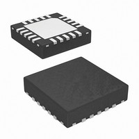
ISL59603IRZ-T7 Intersil, ISL59603IRZ-T7 Datasheet - Page 23

ISL59603IRZ-T7
Manufacturer Part Number
ISL59603IRZ-T7
Description
IC VIDEO EQUALIZER 20-QFN
Manufacturer
Intersil
Series
MegaQ™r
Type
Video Equalizerr
Datasheet
1.ISL59601IRZ-T7.pdf
(27 pages)
Specifications of ISL59603IRZ-T7
Applications
Security Systems, Video Routing
Mounting Type
Surface Mount
Package / Case
20-VFQFN Exposed Pad
Lead Free Status / RoHS Status
Lead free / RoHS Compliant
Available stocks
Company
Part Number
Manufacturer
Quantity
Price
Company:
Part Number:
ISL59603IRZ-T7
Manufacturer:
MEANWELL
Quantity:
200
Additional Equalization Modes Available
With the Serial Interface
In addition to the Lock Until Reset and Continuous
Update modes, software control of MegaQ™ through the
I2C interface adds a Lock Until Signal Loss mode and a
Manual Equalization mode.
Note: When controlling MegaQ™ through the I2C
interface, the external FREEZE pin must be tied to
ground (logic low). Failure to keep FREEZE at a logic low
will prevent the software controls from working properly.
All of the equalization modes are selected via the two
“Locking Mode/Manual Length Enable” register bits,
0x05[1:0].
CONTINUOUS UPDATE
Continuous Update mode is entered by setting address
0x05[1:0] = 00b. Continuous Update behavior is the
same as described in the stand-alone mode.
LOCK UNTIL RESET
Lock Until Reset mode is entered by setting address
0x05[1:0] = 10b. Lock Until Reset behavior is the
same as described in the stand-alone mode, with the
exception of how to generate a reset.
To generate a reset via software, select Continuous
Update mode and then return to Lock Until Reset
mode (register 0x05[1:0] = 00b then 10b). Toggling
INVERT (either the hardware pin or the software bit) will
not cause a reset/re-equalization event.
LOCK UNTIL SIGNAL LOSS
Lock Until Signal Loss mode is entered by setting
address 0x05[1:0] = 01b. Lock Until Signal Loss can
only be enabled via the I2C interface.
In the Lock Until Signal Loss mode, MegaQ™ will
freeze the equalization once the LOCKED pin goes high
(in the same way as Lock Until Reset). Unlike the
“Settled” state in the Continuous Update mode, only a
signal loss lasting more than 1ms (typical) will cause
MegaQ™ to re-equalize the signal when it returns. In this
sense, the Lock Until Signal Loss mode can be
considered as halfway between the Continuous Update
mode and the Lock Until Reset mode. The Lock Until
Signal Loss mode is useful, for example, when testing
or demonstrating a system by plugging in multiple
different length cables - it eliminates the need to also
generate a reset. To prevent potentially undesired re-
equalization, signal losses lasting less than 1ms (typical)
do not trigger a re-equalization.
ISL59601, ISL59602, ISL59603, ISL59604, ISL59605
23
MANUAL LENGTH
Manual Length mode is entered by setting address
0x05[1:0] = 11b. Manual Length mode allows the
forcing of specific cable lengths, DC gains, etc. (see the
Register Listing on the next page). However since many
of MegaQ™’s automatic functions and adjustments are
disabled in Manual Length mode, performance is
almost always worse than what is achieved in any of the
automatic modes. For example, automatic polarity
correction is disabled so the polarity must be manually
set using the INVERT bit. There is no practical reason to
ever use Manual Length mode in normal operation.
Serial Interface Protocol
While MegaQ™ is designed to work as a stand-alone
equalizer, it does have a serial interface that can be used
to control it and monitor its state.
The serial interface is used to read and write the
configuration registers. It uses three signals (SCK, SD,
and SEN) for programming. The serial clock can operate
up to 5MHz (5Mbits/s). The “Serial Timing Diagram” on
page 8 shows the timing of serial I/O.
A transaction begins when the host microcontroller takes
SEN (serial enable) high. The first 8 bits on the SD (serial
data) pin are latched by MegaQ™ on the rising edge of
SCK (serial clock) to form the address byte. The MSB of
the address byte indicates whether the operation is a
read (1) or a write (0), and the next seven bits indicate
which register is to be read from or written to. Each read
and write operation consists of 16 bits: 8 bits for an
address byte followed by 8 bits of data. See the “Serial
Timing Diagram” on page 8 for more details on using the
SPI interface.
WRITE OPERATION
After the address byte is clocked in, the next 8 bits
should contain the data to be sent to the register
identified in the address byte.
READ OPERATION
After the rising edge of the 8th clock after the address byte
is clocked in, the microcontroller should tristate the SD line
so MegaQ™ can begin to output data on the SD pin (from
the register identified in the address byte), beginning on
the 9th rising edge of SCK. The data should be latched on
the falling edge of SCK to allow enough time for the data to
settle. See ““Serial Timing Diagram” on page 8 for more
details on how to read from the registers.
0 = Write
1 = Read
(MSB)
TABLE 2. ADDRESS BYTE FORMAT
A6
A5
A4
A3
A2
November 23, 2010
A1
FN6739.1
(LSB)
A0


