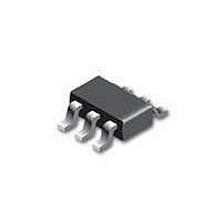
NC7WZ07FHX Fairchild Semiconductor, NC7WZ07FHX Datasheet - Page 5

NC7WZ07FHX
Manufacturer Part Number
NC7WZ07FHX
Description
IC BUFFER UHS DUAL OD 6-MICROPAK
Manufacturer
Fairchild Semiconductor
Datasheet
1.NC7WZ07P6X.pdf
(9 pages)
Specifications of NC7WZ07FHX
Supply Voltage (max)
7 V
Supply Voltage (min)
- 0.5 V
Maximum Operating Temperature
+ 85 C
Mounting Style
SMD/SMT
Package / Case
SC-70-6
Lead Free Status / RoHS Status
Lead free / RoHS Compliant
© 2000 Fairchild Semiconductor Corporation
NC7WZ07 • Rev. 1.0.6
AC Electrical Characteristics
Note:
5.
Notes:
6.
7.
Note:
8.
9.
Symbol
t
PZL
C
C
C
OUT
, t
PD
IN
C
current consumption (I
operating current by the expression: I
Input PRR = 1.0MHz, t
Input=AC Waveform; t
PRR=Variable; Duty Cycle=50%.
C
PLZ
PD
L
includes load and stray capacitance.
is defined as the value of the internal equivalent capacitance which is derived from dynamic operating
Propagation Delay
Input Capacitance
Output Capacitance
Power Dissipation
Capacitance
Parameter
Figure 5. AC Test Circuit
(5)
r
CCD
W
=t
= 500ns.
f
=1.8ns.
) at no output loading and operating at 50% duty cycle. C
2.50 ± 0.20
3.30 ± 0.30
5.00 ± 0.50
2.50 ± 0.20
3.30 ± 0.30
5.00 ± 0.50
1.65
1.80
1.65
1.80
3.30
5.00
V
0
0
CC
CCD
C
RU=500
RD=500
V
C
RU=500
RD=500
V
Conditions
Figure 7. I
=(C
I
I
L
L
=2 x V
=2 x V
=50pF,
=50pF,
PD
)(V
CC
CC
CC
)(f
CCD
IN
5
)+(I
Test Circuit
Min.
1.8
1.8
1.2
0.8
0.5
1.8
1.8
1.2
0.8
0.5
CC
T
static).
A
=+25°C
Typ.
6.6
5.5
3.7
2.9
2.3
5.5
4.3
2.8
2.1
1.4
2.5
4.0
3
4
Figure 6. AC Waveforms
Max.
11.5
11.5
9.5
5.8
4.4
3.5
9.5
5.8
4.4
3.5
Min.
1.8
1.8
1.2
0.8
0.5
1.8
1.8
1.2
0.8
0.5
T
PD
A
+85°C
=-40 to
is related to I
Max.
12.6
10.5
12.6
10.5
6.4
4.8
3.9
6.4
4.8
3.9
Units Figure
pF
pF
CCD
ns
www.fairchildsemi.com
dynamic
Figure 5
Figure 6
Figure 7


