MLX90614ESF-DAA Melexis Inc, MLX90614ESF-DAA Datasheet
MLX90614ESF-DAA
Specifications of MLX90614ESF-DAA


Related parts for MLX90614ESF-DAA


MLX90614ESF-DAA Summary of contents
Page 1
... Simple adaptation for 8…16V applications Sleep mode for reduced power consumption Different package options for applications and measurements versatility Automotive grade Ordering Information Part No. MLX90614 (1) Supply Voltage/ Accuracy Reserved medical accuracy Example: MLX90614ESF-BAA 1 Functional diagram M LX90614Ax x: Vdd=4.5...5. MLX90614 SCL U1 SCL SDA SDA ...
Page 2
General description (continued) The MLX90614 is built from 2 chips developed and manufactured by Melexis: The Infra Red thermopile detector MLX81101 • The signal conditioning ASSP MLX90302, specially designed to process the output of IR sensor. • The device is ...
Page 3
Table of Contents 1 Functional diagram .......................................................................................................................................................................................... 1 2 General Description ......................................................................................................................................................................................... 1 General description (continued) ......................................................................................................................................................................... 2 3 Table of Contents............................................................................................................................................................................................. 3 4 Glossary of Terms............................................................................................................................................................................................ 4 5 Maximum ratings.............................................................................................................................................................................................. 4 6 Pin definitions and descriptions....................................................................................................................................................................... 5 7 ...
Page 4
... Exceeding the absolute maximum ratings may cause permanent damage. Exposure to absolute-maximum- rated conditions for extended periods may affect device reliability. 3901090614 Rev 006 MLX90614 family Infra Red Thermometer in TO-39 MLX90614ESF-Axx MLX90614ESF-Bxx MLX90614ESF-Dxx ° ° Page Single and Dual Zone MLX90614KSF-Axx Data Sheet September 30, 2010 ...
Page 5
Pin definitions and descriptions Pin Name SCL / VSS Note: for +12V (+8…+16V) powered operation refer to the Application information section. For EMC and isothermal conditions reasons it is highly ...
Page 6
Electrical Specifications 7.1 MLX90614Axx All parameters are preliminary for T Parameter Symbol External supply Supply current Supply current (programming) Zener voltage Zener voltage POR level POR level V POR hysteresis V V rise time (10 ...
Page 7
Parameter Symbol Input high voltage V IH Input low voltage V Output low voltage SCL leakage I SCL SDA leakage I SDA SCL capacitance SDA capacitance Slave address Wake up request SMBus Request Timeout, low Timeout, high T Acknowledge setup ...
Page 8
MLX90614Bxx, MLX90614Dxx All parameters are preliminary for T Parameter Symbol External supply V DD Supply current I DD Supply current I DDpr (programming) Sleep mode supply Isleep current Sleep mode supply Isleep current POR level V POR_up POR level ...
Page 9
Parameter Symbol Input high voltage V (Ta,V) IH Input low voltage V (Ta,V) IL Output low voltage V OL SCL leakage I ,leak SCL SDA leakage I ,leak SDA SCL capacitance C SCL SDA capacitance C SDA Slave address SA ...
Page 10
Detailed description 8.1 Block diagram 81101 90302 8.2 Signal processing principle The operation of the MLX90614 is controlled by an internal state machine, which controls the measurements and calculations of the object and ambient temperatures and does the post-processing ...
Page 11
Block description 8.3.1 Amplifier A low noise, low offset amplifier with programmable gain is used for amplifying the IR sensor voltage. By carefully designing the input modulator and balanced input impedance, an offset below 0.5µV is achieved. 8.3.2 Supply ...
Page 12
PWM period configuration: Period in extended PWM mode is twice the period in single PWM mode. In single PWM mode period 1.024*P [ms], where P is the number, written in bits 15…9 PWMCTRL. Maximum period is then ...
Page 13
Check www.melexis.com for latest application notes with details on EEPROM settings. On-chip filtering and settling time: The MLX90614 features configurable on-chip digital filters. They allow customization for speed or noise. Factory default configurations and the typical settling time and noise ...
Page 14
RAM It is not possible to write into the RAM memory. It can only be read and only a limited number of RAM registers are of interest to the customer. Melexis reserved … Melexis reserved Raw data IR channel ...
Page 15
Note*: This address is readable and writable. Bit 3 should not be altered as this will cancel the factory calibration. Note**: EEPROM error signaling is implemented in automotive grade parts only. 8.4.2 Differences with the standard SMBus specification (reference [1]) ...
Page 16
START, REPEATED START, STOP, ACK, and NACK bits. The PEC is a CRC-8 with polynomial X8+X2+X1+1. The Most Significant Bit of every byte is transferred first. 8.4.3.1.1 Read Word (depending on the command – RAM or EEPROM ...
Page 17
AC specification for SMBus 8.4.4.1 Timing The MLX90614 meets all the timing specifications of the SMBus [1]. The maximum frequency of the MLX90614 SMBus is 100 KHz and the minimum is 10 KHz. The specific timings in MLX90614’s SMBus ...
Page 18
Bit transfer SCL PWM/SDA The data on PWM/SDA must be changed when SCL is low (min 300ns after the falling edge of SCL). The data is fetched by both MD and SDs on the rising edge of the SCL. ...
Page 19
Sleep Mode The MLX90614 can enter in Sleep Mode via the command “Enter SLEEP mode” sent via the SMBus interface. This mode is not available for the 5V supply version. To limit the current consumption to 2.5uA (typical), the ...
Page 20
EEPROM. Details on embedded filtering are available in application note “Understanding MLX90614 on-chip digital signal filters”, available from SCL line is kept low in order to reduce current leakage trough the pin (artificial Zener diode is connected to that pin). ...
Page 21
PWM The MLX90614 can be read via PWM or SMBus compatible interface. Selection of PWM output is done in EEPROM configuration (factory default is SMBus). PWM output has two programmable formats, single and dual data transmission, providing single wire ...
Page 22
Single PWM format In single PWM output mode the settings for PWM1 data only are used. The temperature reading can be calculated from the signal timing as: where Tmin and Tmax are the corresponding rescale coefficients in EEPROM for ...
Page 23
Extended PWM format The PWM format for extended PWM is shown in Figure 15. Note that with bits DUAL[5:1]>00h each period will be outputted 2N+1 times, where N is the decimal value of the number written in DUAL[5:1] (DUAL[5:1] ...
Page 24
Example (see Figure 15 above): Configuration: Sensor1 = Ta, Sensor2 = 0° C => [EEPROM] = 100*(Ta min range Ta = +60° C => [EEPROM] = 100*(Ta max range Ta [EEPROM 0x03]=0x993C ...
Page 25
Switching Between PWM and SMBus communication 8.6.1 PWM is enabled The diagram below illustrates the way of switching to SMBus if PWM is enabled (factory programmed POR default for MLX90614 is SMBus, PWM disabled). Note that the SCL pin ...
Page 26
Computation of ambient and object temperatures The IR sensor consists of serial connected thermo-couples with cold junctions placed at thick chip substrate and hot junctions, placed over thin membrane. The IR radiation absorbed from the membrane heats (or cools) ...
Page 27
Processing ambient temperature includes: Offset measurement with fixed length FIR filter Additional filtering with fixed length IIR filter. The result is stored into RAM as T Temperature sensor measurement using programmable length FIR *. Offset compensation Additional processing with programmable ...
Page 28
Thermal relay The MLX90614 can be configured to behave as a thermo relay with programmable threshold and hysteresis on the PWM/SDA pin. The input for the comparator unit of the relay is the object temperature from sensor 1 The ...
Page 29
Unique Features • The MLX90614 is a ready-to use low-cost non contact thermometer provided from Melexis with output data linearly dependent on the object temperature with high accuracy and extended resolution. • The high thermal stability of the MLX90614-XCX ...
Page 30
Performance Graphs 10.1 Temperature accuracy of the MLX90614 10.1.1 Standard accuracy All accuracy specifications apply under settled isothermal conditions only. Furthermore, the accuracy is only valid if the object fills the FOV of the sensor completely. 380 To, o ...
Page 31
Medical accuracy A version of the MLX90614 with accuracy suited for medical applications is available. The accuracy in the range Ta 10ºC - 40ºC and To 32ºC - 42ºC is shown in diagram below. The accuracy for the rest ...
Page 32
The VDD dependence of the ambient and object temperature is 0.6 C/V. -0.10 -0.20 -0.30 -0.40 -0.50 Figure 23: Typical Ta dependence from supply voltage Example: As the devices are calibrated at VDD=3V the error at VDD=3V is smallest one. ...
Page 33
Field Of View (FOV) Point heat source Rotated sensor Parameter MLX90614xAA MLX90614xBA Peak ±0 zone 1 Width 90 zone 1 Peak zone 2 Not applicable Width zone 2 3901090614 Rev 006 Infra Red Thermometer in TO-39 100% 50% Angle ...
Page 34
Figure 28: Typical FOV of MLX90614xBA 3901090614 Rev 006 Infra Red Thermometer in TO-39 Angle, Deg -40 - Figure 27: Typical FOV ...
Page 35
Rev 006 Infra Red Thermometer in TO-39 Angle, Deg -40 -20 0 Figure 30: Typical FOV of MLX90614xCC -40 -20 0 Figure 31: Typical FOV ...
Page 36
Rev 006 Infra Red Thermometer in TO-39 -40º -20º 0º Figure 32: Typical FOV of MLX90614xCH -40º -20º 0º Figure 33: Typical FOV of MLX90614xCI ...
Page 37
Applications Information 11.1 Use of the MLX90614 thermometer in SMBus configuration C1 0.1uF Error! Reference source not found. shows the connection of a MLX90614 to a SMBus with 3.3V power supply. The MLX90614 has diode clamps SDA/SCL to Vdd ...
Page 38
PWM output operation Using the PWM output mode of the MLX90614 is very simple, as shown in Figure 36. Figure 36: Connection of MLX90614 for PWM output mode The PWM mode is free-running after POR when configured in EEPROM. ...
Page 39
The MLX90614 can be configured in EEPROM to operate as a thermal relay. A non contact freezing or boiling prevention with 1 mA quiescent current can be built with two components only – the MLX90614 and a capacitor. The PWM/SDA ...
Page 40
Application Comments Significant contamination at the optical input side (sensor filter) might cause unknown additional filtering/distortion of the optical signal and therefore result in unspecified errors. IR sensors are inherently susceptible to errors caused by thermal gradients. There are ...
Page 41
In case of using the MLX90614Axx internal Zener voltage feature, the regulating external transistor should also not cause heating of the TO39 package. High capacitive load on a PWM line will result in significant charging currents from ...
Page 42
Standard information regarding manufacturability of Melexis products with different soldering processes Our products are classified and qualified regarding soldering technology, solderability and moisture sensitivity level according to following test methods: Wave Soldering THD’s (Through Hole Devices) • EIA/JEDEC JESD22-B106 ...
Page 43
FAQ When I measure aluminum and plastic parts settled at the same conditions I get significant errors on aluminum. Why? Different materials have different emissivity. A typical value for aluminum (roughly polished) is 0.18 and for plastics values of ...
Page 44
This is real optical signal that can not be segregated from the target IR signal and will add errors to the measured temperature. Thermal gradients with impact of that kind are likely ...
Page 45
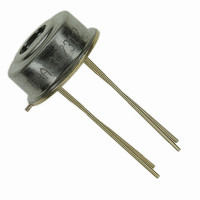
Package Information 16.1 MLX90614XXA The MLX90614 is packaged in an industry standard TO – 39 can. Note: All dimensions are in mm 16.2 MLX90614XCC 3901090614 Rev 006 Infra Red Thermometer in TO-39 Figure 40: MLX90614XXA package Figure 41: MLX90614XCC ...
Page 46
MLX90614XCF 16.4 MLX90614XCH 3901090614 Rev 006 Infra Red Thermometer in TO-39 Figure 42: MLX90614XCF package Figure 43: MLX90614XCH package Page Single and Dual Zone Data Sheet September 30, 2010 ...
Page 47
MLX90614XCI 16.6 Part marking The MLX90614 is laser marked with 10 symbols. First 3 letters define device version (AAA, BCC, etc), and the last 7 are the lot number. Example: “ACC9307308” – MLX90614ACC from lot 9307308. 3901090614 Rev 006 ...
Page 48
Table of figures Figure 1: Typical application schematics........................................................................................................1 Figure 2: Pin description ................................................................................................................................5 Figure 3: Block diagram...............................................................................................................................10 Figure 4: SMBus packet element key...........................................................................................................15 Figure 5: SMBus read word format ..............................................................................................................16 Figure 6: SMBus write word format ..............................................................................................................16 Figure 7: ...
Page 49
References [1] System Management Bus (SMBus) Specification Version 2.0 August 3, 2000 SBS Implementers Forum Copyright . 1994, 1995, 1998, 2000 Duracell, Inc., Energizer Power Systems, Inc., Fujitsu, Ltd., Intel Corporation, Linear Technology Inc., Maxim Integrated Products, Mitsubishi Electric ...