Standard Resistance Range ..................................................................100 to 100K ohms ................................................. 1K to 100K ohms
Total Resistance Tolerance ....................................................................±3 %...................................................................... ±10 %
Independent Linearity ............................................................................±0.2 %................................................................... ±0.2 %
Independent Linearity (Maximum Practical) ..........................................±0.1 %................................................................... ±0.1 %
Effective Electrical Angle .......................................................................3600 ° +10 °, -0 ° .................................................. 3600 ° +10 °, -0 °
Absolute Minimum Resistance/End Voltage .........................................1 ohm or 0.1 % maximum .................................... 0.2 % maximum
Noise/Output Smoothness ...................................................................100 ohms maximum.............................................. 0.10 % maximum
Max. Wiper Current @ 5K ohms ............................................................20 mA ..................................................................... 10 mA
Dielectric Withstanding Voltage (MIL-STD-202, Method 301)
Insulation Resistance (500 VDC) ...........................................................1,000 megohms minimum ..................................... 1,000 megohms minimum
Resolution .............................................................................................See How to Order chart ........................................ Essentially infi nite
Power Rating (Voltage Limited By Power Dissipation)
Operating Temperature Range
Temperature Coeffi cient (Over Static Temperature Range) ...................±50 ppm/°C ............................................................ ±100 ppm/°C
Temperature Cycling (5 Cycles Over Static Temperature Range) .........±2 % TR shift max. ................................................ ±4 % TR shift max.
Vibration (15 Gs, 10 Hz to 2 kHz)
Shock (100 Gs, 6 ms sawtooth)
Load Life (1,000 hours @ 70 °C) ............................................................±2 % TR shift ......................................................... ±5 % TR shift max.
Rotational Life
Moisture Resistance (Mil-Std-202, Method 103) ..................................±2 % TR shift max. ................................................ ±5 % TR shift max.
IP Rating ................................................................................................IP 50 ....................................................................... IP 50
Mechanical Angle .......................................................................................................................................................................................... 3600 ° +10 °, -0 °
Backlash ....................................................................................................................................................................................................................1.0 ° max.
Stop Strength ..................................................................................................................................................................................... 53 N-cm (75 oz-in.) min.
Torque
Shaft Runout T.I.R. ..................................................................................................................................................................................... 0.08 mm (0.003 in.)
Lateral Runout T.I.R. ................................................................................................................................................................................... 0.13 mm (0.005 in.)
Shaft End Play T.I.R. ................................................................................................................................................................................... 0.15 mm (0.006 in.)
Shaft Radial Play T.I.R. ............................................................................................................................................................................... 0.08 mm (0.003 in.)
Pilot Diameter Runout T.I.R. ....................................................................................................................................................................... 0.08 mm (0.003 in.)
Weight
Shaft Side Load (Max. Allowable)
Terminals ............................................................................................................................................................................................. Gold-plated solder lugs
Soldering Condition
Mounting Hardware ........................................................................................... One lockwasher and one mounting nut is shipped with each potentiometer
Recommended Panel Thickness (Bushing Mount) ..................................................................................................................2.46-3.81 mm (0.097-0.150 in.)
Marking .........................................................................................................................Manufacturer’s symbol, model number, product code and date code
Standard Packaging ...........................................................................................................................................................................Plastic trays (5 pcs./tray)
1
For other options, please consult factory.
*RoHS Directive 2002/95/EC Jan 27 2003 including Annex
Specifi cations are subject to change without notice.
Customers should verify actual device performance in their specifi c applications.
At room ambient: +25 °C nominal and 50 % relative humidity nominal, except as noted.
Electrical Characteristics
Sea Level ...........................................................................................1,000 VAC minimum............................................... 1,000 VAC minimum
+70 °C................................................................................................2 watts .................................................................... 2 watts
+125 °C..............................................................................................0 watt ..................................................................... 0 watt
Environmental Characteristics
Dynamic .............................................................................................-40 °C to +125 °C .................................................. -40 °C to +125 °C
Static .................................................................................................-55 °C to +125 °C .................................................. -55 °C to +125 °C
Wiper Bounce ....................................................................................0.1 ms max............................................................. 0.1 ms max.
Wiper Bounce ....................................................................................0.1 ms max............................................................. 0.1 ms max.
No Load .............................................................................................2,000,000 shaft revolutions ................................... 5,000,000 shaft revolutions
Powered (MIL-PRF-12934) ................................................................2,000,000 shaft revolutions ................................... 5,000,000 shaft revolutions
Mechanical Characteristics
Starting ....................................................................................................................................................................................... 0.5 N-cm (0.7 oz.-in.) max.
Running ...................................................................................................................................................................................... 0.5 N-cm (0.7 oz.-in.) max.
Clutch .............................................................................................................................................................................. 1.0 to 4.2 N-cm (1.5 to 6.0 oz.-in.)
Mounting..........................................................................................................................................................................170-200 N-cm (15-18 in.-lb.) max.
Single ...................................................................................................................................................................................................... 20 gm (0.7 oz.) typ.
Dual ....................................................................................................................................................................................................... 36 gm (1.27 oz) typ.
Nickel Plated Brass Shaft w/Brass Bushing ................................................................................................................................................. 50 gmf (1.7 ozf)
Stainless Steel Shaft w/Bronze Bushing .................................................................................................................................................... 250 gmf (8.8 ozf)
Manual Soldering .......................................................... 96.5Sn/3.0Ag/0.5Cu solid wire or no-clean rosin cored wire, 370 °C (700 °F) max. for 3 seconds
Wave Soldering...................................................................................96.5Sn/3.0Ag/0.5Cu solder with no-clean fl ux, 260 °C (500 °F) max. for 5 seconds
Wash processes ...................................................................................................................................................................................... Not recommended
(whichever is greater)
1
1
1
Features
■
■
■
■
■
■
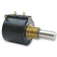
3549 - 10-Turn Precision Potentiometer
Wirewound and Hybritron
High rotational life
Optional 0.1 % linearity
Optional A/R lug
RoHS compliant*
Suitable for use under side load
Wirewound Element
®
elements
■
■
■
Designed for HMI and MMI applications
Dual gang option
Servo mount option
Hybritron
®
Element


